The main types are linear, aligned, angular, radius, diameter, arc length, chordal, ordinate, baseline, chain (continuous), reference, and basic dimensions. Tolerance dimensions are added to show allowable variation.
What Are the Different Types of Dimensions in Technical Drawing?
A technical drawing without dimensions is just a picture. Dimensions are what turn a sketch into a document that a machinist, fabricator, contractor, or inspector can actually build from. If a number is missing, unclear, or placed incorrectly, the result can be scrap parts, failed inspections, change orders, and costly delays.
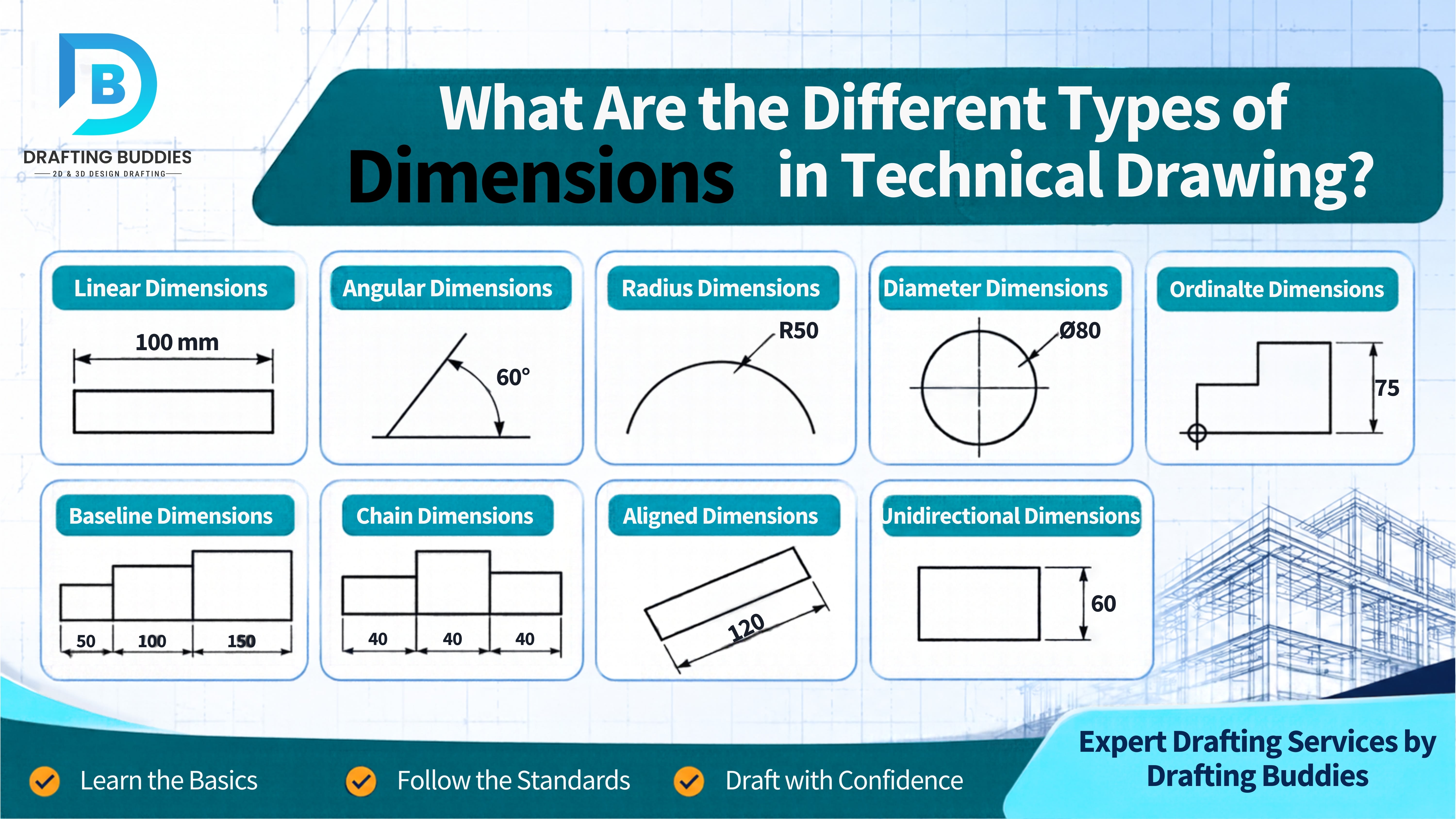
This guide explains every type in plain language, shows when to use each, covers the standards used in the United States and Canada, and finishes with best practices, common mistakes, and frequently asked questions.
Quick Answer: Types of Dimensions at a Glance
| Dimension Type | What It Measures | Typical Use |
|---|---|---|
| Linear | Straight-line distance | Length, width, height, spacing |
| Aligned | Distance parallel to a slanted feature | Angled edges, inclined surfaces |
| Angular | Angle between two lines or surfaces | Chamfers, bevels, bends |
| Radial (Radius) | Distance from center to an arc | Fillets, rounded corners |
| Diameter | Full width of a circle through its center | Holes, shafts, pipes |
| Arc Length | Length measured along a curve | Curved parts, bent sheet metal |
| Ordinate (Datum) | Distances from a common zero point | Hole patterns, plates, PCBs |
| Baseline (Parallel) | Several dimensions from one reference | Stepped parts, hole locations |
| Chain (Continuous) | Dimensions end to end in a row | Repeating features, wall segments |
| Chordal | Straight line between two points on an arc | Arc spans |
| Reference | Informational value, not used for inspection | Cross-checking, clarity |
| Tolerance | Allowed variation from a size | Fits, precision parts |
What Is Dimensioning in Technical Drawing?
Dimensioning is the process of adding measurements, notes, and tolerances to a drawing so that the object can be manufactured or built exactly as the designer intended. A properly dimensioned drawing answers three questions without any guesswork:
- How big is each feature? (size)
- Where is each feature located? (position)
- How accurate does it need to be? (tolerance)
Dimensioning applies across every discipline: mechanical engineering, architecture, civil engineering, structural steel, MEP (mechanical, electrical, plumbing), sheet metal, product design, and BIM documentation.
What Are the Different Types of Dimensions in Technical Drawing?
The Parts of a Dimension
Before looking at the types, it helps to know the building blocks that appear in almost every dimension:
- Extension lines: Thin lines that extend from the feature to show where the measurement begins and ends. They do not touch the object; a small gap is left.
- Dimension line: The line with arrowheads (or tick marks in architectural work) that shows the direction and extent of the measurement.
- Arrowheads or terminators: Mark the endpoints of the dimension. Mechanical drawings use filled arrowheads; architectural drawings often use slashes, dots, or open arrows.
- Dimension text: The number itself, including units, tolerances, and symbols.
- Leader line: An angled line that connects a note or dimension to a feature, commonly used for holes and radii.
- Symbols: Characters such as Ø (diameter), R (radius), ⌓ (arc length), and □ (square) that clarify what is being measured.
Main Types of Dimensions in Technical Drawing
1. Linear Dimensions
Linear dimensions show the straight-line distance between two points. They are the most common type and are used for length, width, height, depth, and thickness. Linear dimensions can be:
- Horizontal: measured left to right
- Vertical: measured top to bottom
- Aligned: measured parallel to an angled edge
- Rotated: measured at a specified angle
Example: A steel plate drawn at 12" long by 6" wide will show two linear dimensions, one for each direction.
2. Aligned Dimensions
When a feature is slanted, a horizontal or vertical dimension would not show its true length. An aligned dimension runs parallel to the edge being measured, so the number reflects the real distance. They are widely used for angled walls, inclined surfaces, and diagonal members.
3. Angular Dimensions
Angular dimensions describe the angle between two lines or surfaces. They are shown with an arc and an arrowhead at each end, and the value is given in degrees (for example, 45°) or degrees, minutes, and seconds for high-precision work (for example, 30° 15' 00").
Where used: chamfers, bevels, roof pitches, bend angles in sheet metal, welding joint preparation, and tapered features.
4. Radius Dimensions
A radius dimension gives the distance from the center of an arc to its edge. It is marked with the letter R before the value (for example, R10). Radius dimensions are used for rounded corners, fillets, and partial arcs.
Tip: Use a radius for arcs of 180° or less. Use a diameter for full circles.
5. Diameter Dimensions
A diameter dimension gives the full width of a circle passing through its center. It is marked with the symbol Ø (for example, Ø25). Diameters are used for holes, shafts, pins, pipes, cylinders, and bolts.
On drawings of cylindrical parts, the diameter is usually dimensioned in the side (rectangular) view, while holes are dimensioned in the circular view with a leader line.
6. Arc Length Dimensions
Arc length dimensions measure the distance along a curved edge, not the straight line between its endpoints. They are marked with an arc symbol above the value. These dimensions are important in bent sheet metal, curved architectural elements, tracks, and cams.
7. Chordal Dimensions
A chordal dimension is the straight-line distance between two points on an arc. It is useful when you need to define the span or opening of a curved feature without calculating its length along the curve.
8. Ordinate (Datum or Coordinate) Dimensions
Ordinate dimensions measure every feature from a single zero point called the datum or origin. Instead of dimension lines with arrowheads, each feature has a single extension line and a number showing its distance from the datum along the X or Y axis.
Advantages:
- Cleaner, less cluttered drawings
- Easy to read for plates with many holes
- Ideal for CNC machining, laser cutting, and PCB layouts
- Reduces cumulative error
9. Baseline (Parallel) Dimensions
Baseline dimensions are a series of dimensions that all start from the same reference line or surface. Each dimension is stacked above or beside the previous one, with the longest placed farthest out.
Advantages: Errors do not accumulate, because every feature is measured from the same starting point. This makes baseline dimensioning the preferred choice for precision parts.
10. Chain (Continuous) Dimensions
Chain dimensions are placed end to end in a line, with each dimension starting where the last one ends. They are simple to read and common in architectural drawings, such as wall segments, door and window openings, and column spacing.
Caution: Tolerances can stack up in chain dimensioning. If each of five segments has a tolerance of ±0.01", the overall length can vary by as much as ±0.05". For tight tolerances, use baseline or ordinate dimensioning instead.
11. Reference Dimensions
A reference dimension is shown for information only and is not used to manufacture or inspect the part. It is written in parentheses, for example (45.5), or marked REF. Reference dimensions help the reader cross-check values without creating a second, conflicting requirement.
12. Basic Dimensions
In geometric dimensioning and tolerancing (GD&T), a basic dimension is a theoretically exact value shown inside a rectangular box. It defines the exact location or shape of a feature, and the allowable variation is controlled separately by a geometric tolerance, such as position or profile.
Types of Dimensions by Purpose
The types above describe the form of a dimension. Drafters also classify dimensions by what they communicate.
Size Dimensions
Size dimensions describe how large a feature is: the diameter of a hole, the thickness of a plate, the width of a slot, or the height of a wall.
Location Dimensions
Location dimensions describe where a feature sits in relation to others or to a datum, such as the distance from the edge of a plate to the center of a hole, or the spacing between two columns.
Overall Dimensions
Overall dimensions give the total length, width, and height of the object or assembly. They are essential for packaging, shipping, space planning, and checking fit within an enclosure or building footprint.
Detail Dimensions
Detail dimensions describe the smaller features within an object, such as chamfers, grooves, notches, steps, and fillets.
Functional, Non-Functional, and Auxiliary Dimensions
- Functional dimensions directly affect how the part performs or fits with mating parts.
- Non-functional dimensions do not affect function but are needed for manufacturing or appearance.
- Auxiliary (reference) dimensions are informational only.
Tolerance Dimensions: How Much Variation Is Allowed?
No part can be made perfectly to size, so drawings specify how much variation is acceptable. There are three common ways to show tolerance:
- Bilateral tolerance: Variation is allowed in both directions, for example 25.00 ± 0.05.
- Unilateral tolerance: Variation is allowed in only one direction, for example 25.00 +0.05 / −0.00.
- Limit dimensions: The upper and lower limits are stated directly, for example 24.95 / 25.05.
For fits between mating parts (such as a shaft in a bearing), drawings may also use standardized fit classes, including clearance, transition, and interference fits.
Geometric Dimensioning and Tolerancing (GD&T)
GD&T goes beyond size tolerances. It uses symbols in feature control frames to control form, orientation, location, profile, and runout, including flatness, straightness, perpendicularity, parallelism, concentricity, position, and more. GD&T is standard in aerospace, automotive, medical device, and precision manufacturing, and it is defined in the United States by ASME Y14.5.
Dimensioning Systems: Aligned vs. Unidirectional
There are two ways to orient dimension text on a drawing:
- Aligned system: Text is placed parallel to the dimension line. Horizontal dimensions read left to right, and vertical dimensions read from the right side of the sheet. This is traditional in architectural and structural work.
- Unidirectional system: All text reads horizontally, regardless of the dimension line direction. This is the standard in most modern mechanical drawings and is easier to read.
Units of Measurement: USA vs. Canada
Choosing the correct units is critical when drawings cross the border.
- United States: Mechanical drawings typically use decimal inches (for example, 2.500"). Architectural and construction drawings use feet and inches with fractions (for example, 12'-6 1/2"). Metric (SI) is also common in some industries.
- Canada: Metric units (millimeters and meters) are the official standard, but many projects, especially those tied to US clients or suppliers, also use imperial units. Drawings should always state the unit clearly.
Best practice: Include a general note such as "ALL DIMENSIONS ARE IN MILLIMETERS UNLESS OTHERWISE NOTED" or "ALL DIMENSIONS ARE IN INCHES UNLESS OTHERWISE NOTED". For dual-unit drawings, show the secondary unit in brackets.
Standards That Govern Dimensioning
Using a recognized standard keeps drawings consistent and legally defensible.
- ASME Y14.5: The primary US standard for dimensioning and tolerancing (including GD&T) on engineering drawings.
- ASME Y14.3 and Y14.41: Cover multiview and sectional drawings and digital product definition practices.
- ISO 129-1: The international standard for dimensioning principles.
- ISO GPS (ISO 1101 and related): International standards for geometrical product specifications.
- CSA B78.2: The Canadian standard for dimensioning and tolerancing of technical drawings.
- National CAD Standard (NCS) and AIA guidelines: Commonly followed for architectural drawings in the USA.
- Provincial and local building codes: Affect how dimensions are shown on permit drawings in Canada and the USA.
Always confirm which standard the client, contractor, or authority having jurisdiction requires before starting.
Types of Dimensions by Industry
Mechanical and Manufacturing
Relies heavily on linear, diameter, radius, ordinate, and baseline dimensions, along with tolerances and GD&T. Precision and repeatability are the priority.
Architectural
Uses chain dimensions, overall building dimensions, grid line spacing, room dimensions, and opening dimensions. Dimensions are typically shown to the face of stud, face of concrete, or centerline of structure, so the reference point should always be noted.
Structural and Civil
Uses grid-based dimensioning, elevations, slopes, offsets, and station-based dimensions for roads and utilities.
MEP and BIM
Uses dimensions for equipment clearances, duct and pipe routing, elevations above finished floor, and coordination offsets. In BIM, many dimensions are driven by the model itself, which reduces manual error.
Sheet Metal and Fabrication
Uses bend angles, flat pattern lengths, hole-to-edge distances, and arc lengths. Bend allowances and tolerances must be considered.
Rules for Good Dimensioning
Follow these rules to keep your drawings clear, accurate, and professional:
- Dimension each feature once. Duplicate dimensions create conflicts and confusion.
- Place dimensions outside the object whenever possible, in the view where the feature appears most clearly (the "contour view").
- Keep dimensions off hidden lines. Dimension visible features only.
- Do not cross dimension lines or extension lines unless unavoidable.
- Stack dimensions neatly. Put smaller dimensions closer to the object and larger ones farther out.
- Use consistent spacing (typically about 10 mm or 3/8" between parallel dimension lines).
- Leave a small gap between the object and the start of each extension line.
- Use consistent units, and state them in a general note.
- Do not close-chain every dimension. Omit one dimension in a chain when an overall dimension is given, or mark it as a reference.
- Give every dimension needed to build the part, and no more. The reader should never have to measure from the drawing or calculate a missing value.
- Use leader lines clearly, and avoid long or crossing leaders.
- Choose text height for readability, typically 1/8" (3 mm) minimum on standard sheets.
- Apply tolerances deliberately. Tighter tolerances cost more, so specify only what the function requires.
- Use standard symbols (Ø, R, □, ⌓, ∠) to remove ambiguity.
Common Dimensioning Mistakes to Avoid
- Missing dimensions that force the shop or site to guess
- Over-dimensioning, where the same feature is dimensioned in multiple places
- Conflicting dimensions between views or sheets
- Dimensions placed on hidden features
- Mixing metric and imperial units without notes
- Unclear datums or reference points
- Cluttered drawings with overlapping text and lines
- Using chain dimensions where tolerance stack-up will cause problems
- Forgetting to dimension overall sizes
- Using unrealistic tolerances that raise manufacturing cost
- Leaving default CAD dimension values that do not match the actual design
How CAD and BIM Software Handle Dimensions
Modern CAD tools such as AutoCAD, SolidWorks, Inventor, Fusion 360, Revit, and MicroStation include automatic dimensioning tools. They can create linear, aligned, angular, radius, diameter, ordinate, baseline, and continuous dimensions with a few clicks and update them as the design changes.
Still, software only follows your settings. Always check:
- Dimension styles: text height, arrow type, units, precision, and tolerance format
- Annotative scaling: so dimensions print at the correct size in each viewport
- Associativity: so dimensions update when geometry changes
- Overrides: manually typed values can hide model errors and should be avoided
In BIM workflows, dimensions are tied to the model, so coordination and revisions are faster and more reliable. However, drawings still need clear, readable dimension strings and notes for permit review and construction.
Why Accurate Dimensioning Matters for Your Project
Good dimensioning does more than make a drawing look neat. It:
- Reduces rework and waste by preventing fabrication and construction errors
- Speeds up permit approval because plan reviewers can verify the information easily
- Improves communication between designers, engineers, contractors, and manufacturers
- Lowers project cost by removing RFIs, change orders, and delays
- Supports quality control with clear inspection criteria
- Protects against liability with a clear and consistent record of design intent
Need Help With Dimensioned Technical Drawings?
If you need accurate, standards-compliant drawings for your project, a professional drafting team can save time and reduce risk. Drafting Buddies provides 2D CAD drafting, 3D modeling and BIM, MEP and structural drafting, shop drawings, permit drawings, and as-built drawings for clients across the USA and Canada, with a team that has been serving the AEC industry since 2014.
Get in touch for a free quote on your next drafting project.
Final Thoughts
Understanding the different types of dimensions in technical drawing is the foundation of clear and buildable design documentation. Linear, angular, radius, diameter, ordinate, baseline, and chain dimensions each serve a purpose, and choosing the right one depends on the part, the industry, the tolerance requirements, and the standard you follow.
Start with the essentials: define size, location, and tolerance clearly, follow the right standard for your region, keep units consistent, and never leave the reader guessing. Do that, and your drawings will move through fabrication, permitting, and construction with fewer questions and fewer costly mistakes.
Looking for professional CAD drafting, BIM modeling, or permit-ready drawings for your US or Canadian project? Contact Drafting Buddies today for a free quote.