50 Types of Construction Drawings:
Part 3 (MEP Drawings)
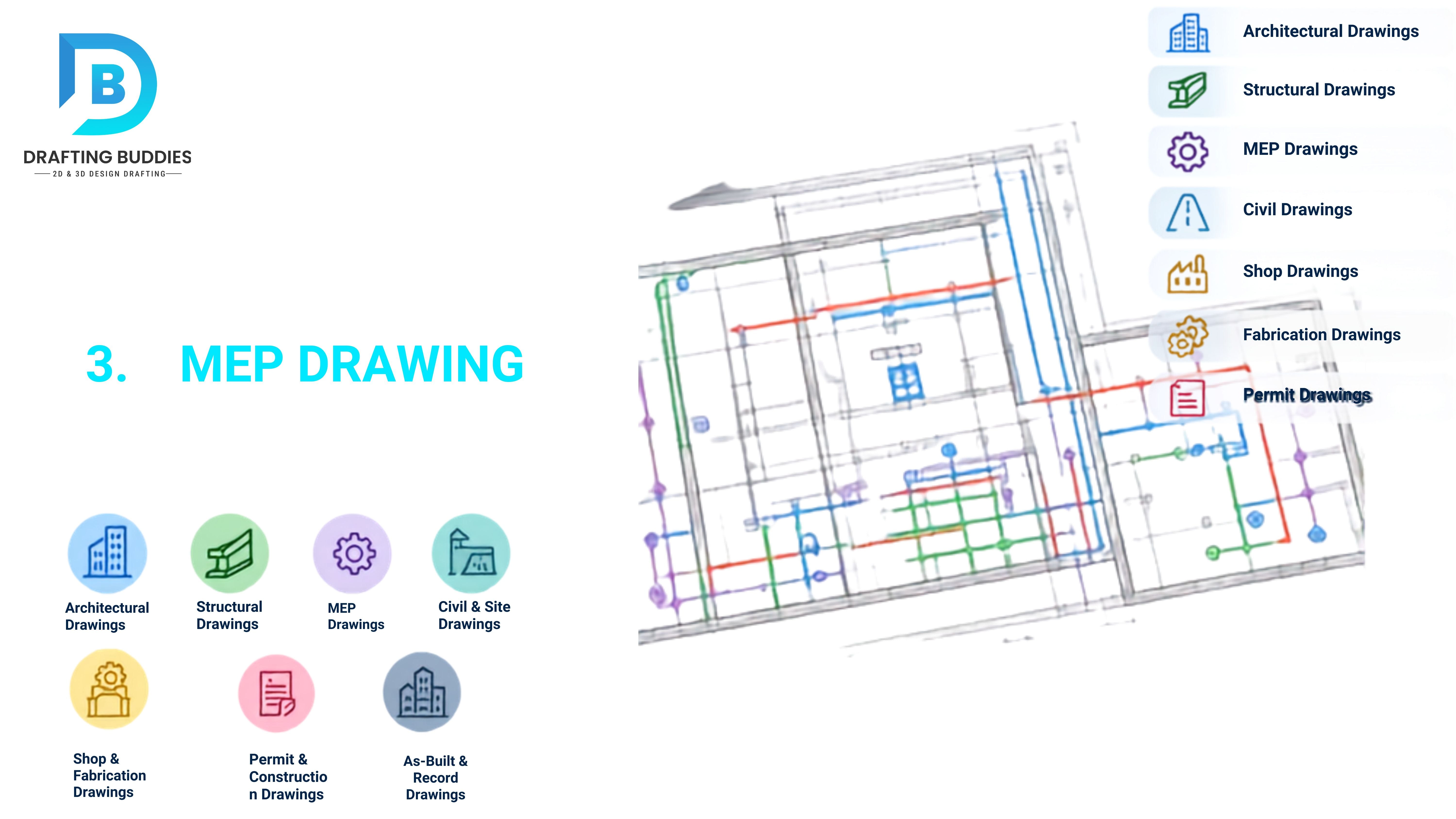
Mechanical, Electrical, and Plumbing drawings make a building livable and functional - and they're the drawings most prone to clashes, since multiple systems compete for the same ceiling space.
- 26.
HVAC Plan (Mechanical)
Shows heating/cooling equipment and airflow layout.
Example: an HVAC plan for a hospital showing air handling units.
Common mistake: Equipment sized for the wrong occupancy load, causing comfort complaints after occupancy.
- 27.
Ductwork Layout
Details duct routing, sizing, and diffuser locations.
Example: a ductwork plan for a retail store ceiling.
Common mistake: Duct routing that clashes with structural beams or sprinkler piping.
- 28.
Plumbing Plan
Shows water supply and drainage piping layout.
Example: a plumbing plan for a multi-family building's riser system.
Common mistake: Vent piping that isn't properly sized or routed, causing code compliance issues at inspection.
- 29.
Piping Isometric Drawings
3D-style single-line views of pipe routing.
Example: an isometric for a commercial kitchen's grease waste line.
Common mistake: Isometrics that don't match the plan-view piping layout, confusing installers in the field.
- 30.
Electrical Power Plan
Shows outlets, panels, and circuit layout.
Example: a power plan for an office floor's workstation outlets.
Common mistake: Circuit loads that exceed panel capacity, discovered only after installation begins.
- 31.
Lighting Plan
Shows fixture types, switching, and controls.
Example: a lighting plan for a warehouse with high-bay fixtures.
Common mistake: Fixture types on the lighting plan that don't match what's shown on the architectural RCP.
- 32.
Fire Protection / Sprinkler Plan
Shows sprinkler head layout and piping for fire suppression.
Example: a sprinkler plan for a big-box retail store.
Common mistake: Sprinkler heads that clash with ductwork or structural members, requiring costly field relocations.
- 33.
Fire Alarm Plan
Shows detection devices, pull stations, and notification appliances.
Example: a fire alarm plan for a school building.
Common mistake: Device spacing that doesn't meet coverage requirements for the actual ceiling height.
- 34.
Low Voltage / Data-Communication Plan
Shows data, security, and AV cabling layout.
Example: a low-voltage plan for a corporate office's network drops.
Common mistake: Low-voltage pathways not coordinated with structural framing, leaving no clear route for cable trays.
- 35.
Single Line Diagram (Electrical)
A simplified schematic showing the electrical distribution system.
Example: a single-line diagram for a building's main switchgear.
Common mistake: Single-line diagrams that aren't updated when electrical loads change during design development.
- 36.
MEP Coordination / Clash Detection Drawings
BIM-based overlays showing where systems conflict before construction.
Example: a clash detection report flagging ductwork routed through a structural beam.
Common mistake: Skipping formal clash detection and relying on field coordination, which is far more expensive to fix.
Why MEP coordination is the hardest part
Architectural and structural drawings mostly avoid each other's space. MEP systems don't have that luxury - which is exactly why BIM-based clash detection has become standard practice.