LOD stands for Level of Development. Some teams also use it to mean Level of Detail, but Level of Development is the more precise and widely accepted meaning because it reflects how reliable the information is, not only how detailed it looks.
LOD 100 vs. LOD 200 vs. LOD 300 vs. LOD 400: What Is the Difference?
LOD (Level of Development) tells every team member how far a model element has been developed and how much they can rely on it.
LOD 100 is a concept, LOD 200 is approximate geometry, LOD 300 is accurate enough for construction documents, and LOD 400 is fabrication-ready.
The right LOD is the one your project stage and deliverables actually require, not always the highest one.
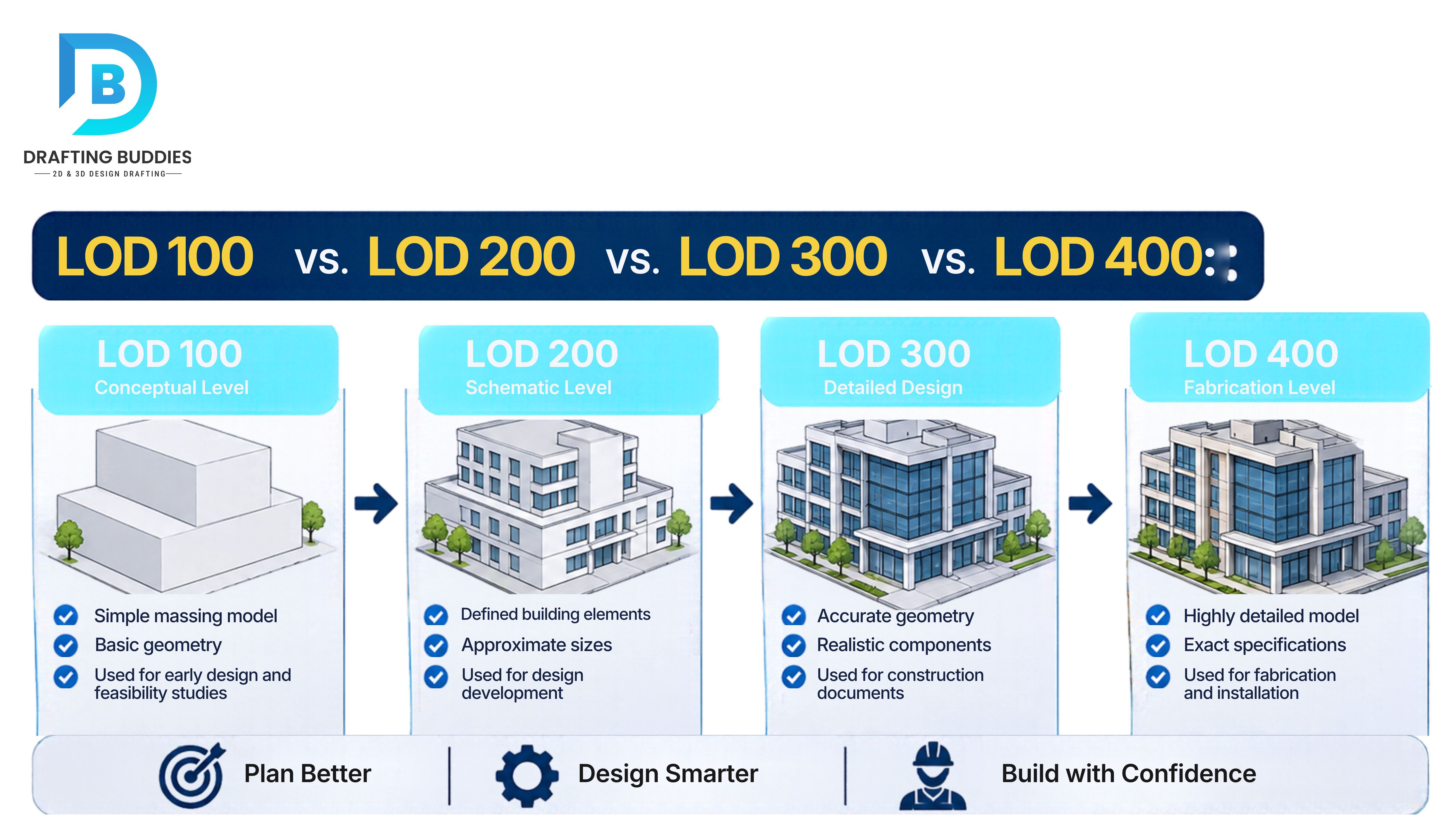
What Is LOD in BIM?
In Building Information Modeling, LOD stands for Level of Development. It tells every team member how far a model element has been developed and how much they can rely on it.
Think of it as a promise. If a column is modeled at LOD 300, the team can trust that its size, shape, and location are accurate enough to produce construction documents. If it is modeled at LOD 200, they should treat it as an approximation that will still change.
LOD solves a very common problem in construction: two people looking at the same model, with different assumptions about how accurate it is. By agreeing on LOD before work begins, architects, engineers, contractors, and owners avoid misunderstandings, rework, and disputes.
Two points are worth remembering:
- LOD is assigned to individual model elements, not to the entire building model.
- LOD describes development, not just appearance. A model element can look detailed yet still be unreliable. LOD reflects how much the information can be trusted.
LOD vs. LOI: Geometry and Information
You will often see two related terms:
- LOD (Level of Detail or Development): how detailed and accurate the geometry is.
- LOI (Level of Information): how much non-graphical data the element carries, such as material, manufacturer, fire rating, cost code, and maintenance data.
A wall can have simple geometry (low LOD) but rich data attached (high LOI), or the reverse. In practice, project teams define both so the model delivers the right shape and the right information.
In the United States, "LOD" is commonly used to mean Level of Development, following the framework published by BIMForum and the AIA. In the UK and other regions that follow ISO 19650, the term "Level of Information Need" is used. Always check which definition your project follows.
LOD 100 Explained
LOD 100 is the conceptual level.
At this stage, model elements are shown as symbols, simple masses, or placeholders. They indicate that something will exist, but not exactly what it is.
What it includes:
- Building massing and overall volume
- Approximate height, area, orientation, and location
- Generic symbols for systems or equipment
- Cost information based on area or volume (for example, cost per square foot)
What it does not include:
- Accurate dimensions
- Specific products or materials
- Detailed connections
Typical uses:
- Early feasibility studies
- Site and zoning analysis
- Massing and concept design
- Preliminary budgeting
LOD 200 Explained
LOD 200 is the approximate geometry level.
Elements are now modeled as generic objects with approximate size, shape, location, and orientation. Systems are recognizable, but they are not yet detailed or exact.
What it includes:
- Generic walls, floors, roofs, and openings with approximate dimensions
- Major structural elements with estimated sizes
- Main ductwork, piping, and equipment shown as approximate placeholders
- Non-geometric information such as general material type or estimated performance
What it does not include:
- Final dimensions
- Detailed connections and supports
- Manufacturer-specific products
Typical uses:
- Schematic design
- Preliminary MEP and structural coordination
- Early cost estimating and area takeoffs
- Design option comparison
LOD 300 Explained
LOD 300 is the accurate geometry level and the standard for construction documents.
Elements are modeled as specific, dimensioned objects. Their size, shape, quantity, location, and orientation can be measured directly from the model without relying on notes or separate annotations.
What it includes:
- Accurate walls, doors, windows, floors, stairs, and ceilings
- Structural members with actual sizes, grid locations, and elevations
- MEP systems modeled with real sizes, routing, and primary equipment
- Information attached to elements, such as material, type, and basic performance data
What it does not include:
- Shop-level detail such as fabrication joints, fasteners, or full connection design
- Final manufacturer-specific assemblies in every case
Typical uses:
- Design development
- Construction documents and permit drawings
- Quantity takeoffs and cost estimating
- Standard clash detection between disciplines
LOD 350 Explained
LOD 350 is the coordination level between LOD 300 and LOD 400.
It builds on LOD 300 by adding the elements needed to coordinate with other trades, such as supports, hangers, connections, and clearances. It is not part of the original LOD 100–400 sequence, but it was introduced because real projects need a step between design accuracy and full fabrication detail.
Typical uses:
- Detailed MEP and structural coordination
- Clash detection that accounts for supports, insulation, and access clearances
- Pre-fabrication planning
When a project calls for "coordinated" MEP models, LOD 350 is often what is actually needed.
LOD 400 Explained
LOD 400 is the fabrication and assembly level.
Elements are modeled with enough detail and accuracy for a manufacturer, fabricator, or installer to produce and install them. This includes exact dimensions, connections, fasteners, and assembly sequences.
What it includes:
- Steel members with bolts, welds, plates, and connection details
- Ductwork and piping broken into fabrication spools, with hangers, supports, and fittings
- Rebar placement and detailing for reinforced concrete
- Curtain wall, millwork, and precast components modeled to shop-level detail
- Installation and assembly information
Typical uses:
- Shop drawings
- Prefabrication and modular construction
- CNC and fabrication workflows
- Installation planning
Drafting Buddies provides LOD 400 BIM modeling and shop drawings for the elements that actually need fabrication detail.
LOD 500 Explained
LOD 500 is the field-verified, as-built level.
Elements are modeled to reflect what was actually built and installed, confirmed in the field. Unlike the other levels, LOD 500 is less about additional geometry and more about verification.
Typical uses:
- As-built documentation
- Facility management and maintenance
- Future renovation and retrofit planning
The BIMForum specification does not formally define LOD 500 in the same way as the earlier levels, because it relates to field verification rather than design development. Many teams still use the term to describe as-built deliverables, so confirm the definition in your contract.
LOD 100 vs. 200 vs. 300 vs. 400: Side-by-Side Comparison
| Feature | LOD 100 | LOD 200 | LOD 300 | LOD 400 |
|---|---|---|---|---|
| Name | Conceptual | Approximate geometry | Precise geometry | Fabrication / assembly |
| Geometry | Symbols or simple masses | Generic objects, approximate size and shape | Specific, accurate size, shape, and location | Detailed, shop level with connections |
| Accuracy | Very low | Moderate | High | Very high |
| Data included | Area/volume based data | General type and estimated data | Specific type, material, and performance | Manufacturer, installation, and assembly data |
| Project stage | Concept / feasibility | Schematic design | Design development and construction documents | Fabrication and installation |
| Typical deliverable | Massing model | Preliminary coordination model | Construction documentation model | Shop drawings and fabrication models |
| Cost estimating basis | Cost per area or volume | Approximate quantities | Measured quantities | Exact quantities and assemblies |
| Modeling effort | Lowest | Low to moderate | Moderate to high | Highest |
| Can it be built from directly? | No | No | Not fully | Yes |
Real Examples: A Wall, a Duct, and a Beam at Each LOD
Seeing the same element at each level makes the difference clear.
Example 1: An Interior Wall
- LOD 100: an area or volume placeholder showing that a partition exists.
- LOD 200: a generic wall with approximate thickness and height.
- LOD 300: a wall of the specified type with correct thickness, height, and location, plus layers such as studs, drywall, and insulation defined.
- LOD 400: the wall assembly modeled with framing members, fasteners, blocking, and attachments in their exact positions for installation.
Example 2: An HVAC Duct
- LOD 100: a symbol or allowance for mechanical space.
- LOD 200: a main duct run with approximate size and routing.
- LOD 300: the duct with correct size, routing, elevation, and fittings, ready for coordination and documentation.
- LOD 400: the duct divided into fabrication sections, including hangers, supports, flanges, access doors, and insulation.
Example 3: A Steel Beam
- LOD 100: a generic structural zone.
- LOD 200: a beam with estimated depth and approximate span.
- LOD 300: a beam with the actual designated section, location, and elevation.
- LOD 400: the beam with end plates, bolt holes, welds, stiffeners, and connection details for fabrication.
Which LOD Do You Need? (By Project Stage and Service)
The right LOD depends on what the model is being used for.
These are common starting points, not fixed rules. The owner, designer, and contractor should confirm the requirement for every discipline in the BIM Execution Plan.
| Project Stage / Service | Recommended LOD |
|---|---|
| Feasibility, massing, and early planning | LOD 100 |
| Schematic design and early cost estimates | LOD 200 |
| Architectural, structural, and MEP design development | LOD 300 |
| Construction documents and permit drawings | LOD 300 |
| Clash detection and trade coordination | LOD 300–350 |
| 5D quantity takeoff for bidding | LOD 300 |
| Shop drawings (steel, MEP, millwork, precast) | LOD 400 |
| Prefabrication and modular construction | LOD 400 |
| Scan-to-BIM for renovation | LOD 200–300, depending on the use |
| As-built model for facility management | LOD 300–500, with required data attached |
How LOD Affects Cost, Time, and File Size
Each step up in LOD typically brings:
- More modeling hours: detailed elements take longer to create and check.
- Larger file sizes: more objects and more detail make models heavier to open, coordinate, and share.
- More coordination effort: more detail means more items to review and resolve.
- Higher accuracy and certainty: fewer assumptions and less risk when building.
The goal is to match LOD to need. Modeling everything at LOD 400 on a project that only needs permit drawings wastes budget. Modeling at LOD 200 when a fabricator needs shop drawings creates rework and delays. A well-planned project assigns higher LOD only to the elements and areas where it adds value.
Common LOD Mistakes and How to Avoid Them
| Mistake | Why It Causes Problems | How to Avoid It |
|---|---|---|
| Applying one LOD to the whole model | Wastes time on non-critical elements | Define LOD per element, system, and phase |
| Confusing LOD with how realistic a model looks | A good-looking model can still be unreliable | Judge LOD by accuracy and reliability, not appearance |
| Not defining LOD in the contract | Leads to disputes about scope and deliverables | Include an LOD matrix in the BEP and contract |
| Over-modeling early | Increases cost and slows revisions | Model only what the current stage needs |
| Under-modeling for coordination | Misses clashes with supports, insulation, and clearances | Use LOD 350 for detailed MEP coordination |
| Ignoring LOI | Geometry is correct but required data is missing | Specify both geometry and information requirements |
| Treating LOD 500 as a design level | It reflects field verification, not design detail | Use it for as-built and facility management needs |
Who Defines LOD? Standards and Specifications
Several documents shape how LOD is understood and applied:
- AIA G202 and G203: American Institute of Architects documents that introduced LOD 100–500 and are used to set model development requirements in contracts.
- BIMForum LOD Specification: a detailed, element-by-element reference that illustrates LOD 100 to 400 for building components and is widely used in the United States. It is updated regularly, so check the current version.
- ISO 19650: the international standard for information management using BIM, which uses the concept of Level of Information Need.
- Project-specific BIM Execution Plans: the most important document in practice, because it defines what each party must deliver.
The key point: the contract and BIM Execution Plan decide the required LOD, not the software.
Final Thoughts
Understanding LOD 100, 200, 300, and 400 is one of the most practical ways to improve BIM project outcomes. It sets clear expectations, controls cost, and ensures every model element is reliable enough for its purpose.
The simple rule: use the lowest LOD that fully supports the task, and raise it only where the project truly needs more detail. LOD 100 and 200 guide early decisions, LOD 300 produces construction documents, and LOD 400 supports fabrication and installation.
At Drafting Buddies, we have supported architects, engineers, contractors, and builders across all 50 US states since 2014 with 3D modeling and BIM, MEP and structural drafting, shop drawings, permit drawings, as-built drawings, rendering, and scan-to-BIM services, at the LOD your project requires.
Not sure which LOD your project needs? Contact Drafting Buddies for a free consultation. Share your drawings or project scope, and our team will recommend the right LOD, deliverables, and timeline.
About Drafting Buddies
Founded in Austin, Texas in 2014, Drafting Buddies provides CAD drafting, BIM modeling, and AEC services with an A+ BBB rating to clients across the United States.