It is the process of scanning an existing building with a laser scanner and converting the scan data into an intelligent 3D BIM model that can be used for design, renovation, and facility management.
Scan to BIM: Process, Benefits and Applications
Scan to BIM converts point cloud data from laser scans into a parametric 3D BIM
model with real building elements such as walls, floors, columns, beams, ducts, and pipes.
It is the most reliable way to document existing conditions, especially when original drawings are missing, outdated, or inaccurate.
The process has five main stages: planning, scanning, registration, modeling, and quality control.
Accuracy depends on the scanner, the scanning method, the registration quality, and the agreed LOD and tolerance.
Main applications include renovation and retrofit, MEP coordination, historic preservation, as-built documentation, facility management, and construction verification.
Benefits include fewer site visits, fewer design errors, better clash detection, safer data capture, and a reliable digital record of the building
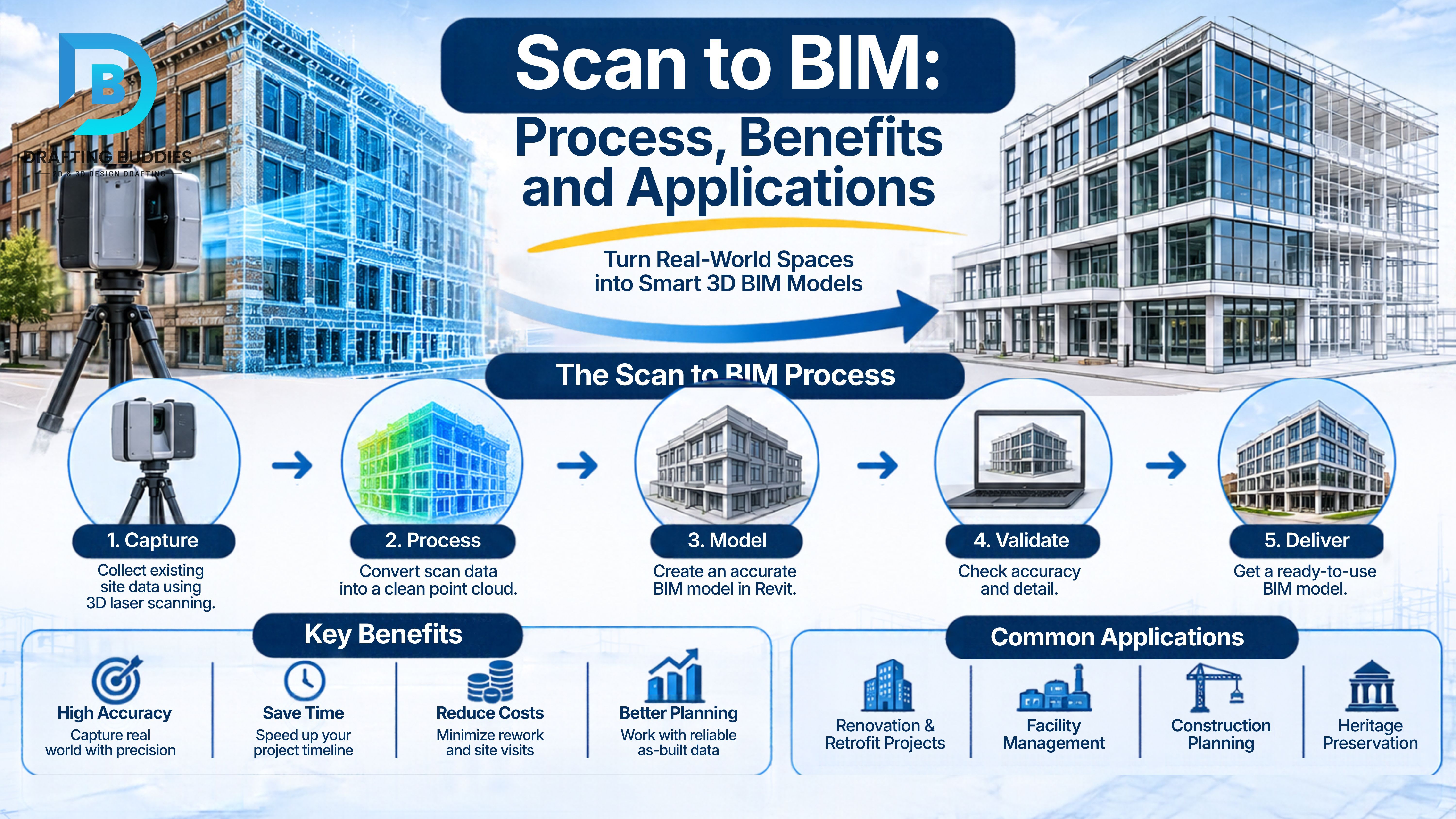
What Is Scan to BIM?
Most buildings were not built from a perfect set of drawings, and even when they were, years of changes, repairs, and renovations rarely make it back into the documents. Anyone planning work on an existing building quickly discovers that the drawings do not match reality.
Scan to BIM solves this problem. The workflow looks like this:
- A 3D laser scanner captures millions of precise measurement points of the building's interior, exterior, or site.
- The result is a point cloud: a dense, three-dimensional collection of points that represents the exact shape of everything the scanner could see.
- BIM specialists use the point cloud as a reference to build an intelligent BIM model, where each element is a real object (a wall, a beam, a duct) and not just a cluster of points.
- The finished model is used for design, documentation, coordination, and long-term management.
Why Scan to BIM Matters
Working from outdated or incomplete drawings is one of the biggest risks in renovation and retrofit projects. Common results include:
- New systems that do not fit in the actual space
- Surprises discovered after demolition begins
- Change orders and delays caused by wrong assumptions
- Repeated site visits to take missing measurements
- Design coordination based on information that is not reliable
Scan to BIM replaces assumptions with measured data. The design team starts with an accurate digital twin of the existing building, which reduces risk before the first drawing is issued.
Key Terms You Should Know
| Term | Meaning |
|---|---|
| Point cloud | A collection of millions of 3D points, each with X, Y, Z coordinates, that records the shape of a space. |
| LiDAR | Light Detection and Ranging, the laser technology used by many scanners to measure distance. |
| Registration | The process of aligning multiple individual scans into one unified, correctly positioned point cloud. |
| Parametric model | A model whose elements follow rules and can be edited through parameters instead of redrawing. |
| LOD | Level of Development, which defines how detailed and reliable each model element is. |
| Tolerance | The allowed difference between the model and the real, measured condition. |
| As-built model | A model that documents the actual existing or completed condition of a building. |
| Photogrammetry | A method that creates 3D data from overlapping photographs. |
| RCP / E57 formats | Common point cloud file formats used to exchange scan data. |
The Scan to BIM Process: Step by Step
- 01
Define Project Goals and Requirements
Every successful project begins with clear answers to a few questions: What will the model be used for? Which areas need to be scanned? What LOD is required for each discipline? What tolerance is acceptable? What file formats and software are needed? These decisions control the cost, time, and accuracy of the whole project.
- 02
Site Assessment and Scan Planning
Before scanning, the team studies the site: building size, access, occupied areas, obstructions, lighting, and safety restrictions. A scan plan defines scanner positions, overlap between scans, and how to cover hidden areas such as ceilings, mechanical rooms, and above-ceiling spaces. Good planning reduces missing data and the need for return visits.
- 03
On-Site Laser Scanning
A scanning technician places the scanner at planned positions throughout the site. At each position, the scanner rotates and captures millions of measurement points in a few minutes. Many scanners also capture colored panoramic images, which help modelers identify materials, equipment, and details later. Reference targets or natural features are used to help align scans.
- 04
Registration and Point Cloud Processing
The individual scans are aligned into a single point cloud that covers the entire building. This stage is called registration. The point cloud is then cleaned by removing noise, moving objects, and stray points, and it is georeferenced or aligned to a project coordinate system. Registration quality has a direct impact on the final model accuracy, so it should always be checked and documented.
- 05
Point Cloud Review and Modeling Setup
The processed point cloud is imported into BIM software such as Autodesk Revit, and the project template, levels, grids, families, and modeling rules are prepared. The team confirms the LOD, naming standards, and level of detail for each element before modeling starts.
- 06
BIM Modeling from the Point Cloud
Modelers trace and build real BIM elements over the point cloud, including:
- Architectural: walls, floors, ceilings, roofs, doors, windows, stairs, and openings
- Structural: columns, beams, slabs, foundations, and framing
- MEP: ducts, pipes, conduits, cable trays, equipment, and fixtures
- Site and facade elements, where required
Each object is placed to match the scan within the agreed tolerance and given the correct type, size, and information.
- 07
Quality Control and Deviation Analysis
The model is checked against the point cloud. Deviation analysis (often shown as a color map) highlights where the model differs from the scanned reality. The team corrects any element that falls outside the allowed tolerance and reviews the model for completeness, naming, and consistency. Skipping this step is a common cause of unreliable as-built models.
- 08
Delivery and Handover
The finished deliverables are issued, usually including the BIM model, point cloud files, 2D plans, sections, elevations, and reports. The model can then move directly into design, coordination, or facility management.
Scanning Technologies and Equipment
Different tools suit different projects.
| Technology | Best For | Notes |
|---|---|---|
| Terrestrial laser scanner (TLS) | Interiors, exteriors, industrial plants, and high-accuracy needs | Tripod-based; the standard for detailed as-built capture. |
| Mobile / handheld scanner (SLAM) | Large or complex interiors where speed matters | Faster capture while walking; accuracy varies by system. |
| Drone (UAV) photogrammetry or LiDAR | Roofs, facades, large sites, and hard-to-reach areas | Useful for exteriors and site context. |
| Photogrammetry (photo based) | Smaller areas, textured detail, and budget-conscious jobs | Lower accuracy than laser scanning in many cases. |
| Total station survey | Control points and precise reference positions | Often used to support scanning. |
The right choice depends on the required accuracy, the building type, access, schedule, and budget.
Accuracy, Tolerance, and LOD
Three concepts control how useful a Scan to BIM model will be.
Accuracy
Accuracy comes from two places: the scan data (equipment, setup, and registration) and the modeling (how closely the model follows the point cloud). Modern terrestrial scanners can capture data to a very small margin, but the final model is only as good as the registration and the modeling process.
Tolerance
Tolerance is the maximum allowed difference between the model and the point cloud. It should be agreed before modeling begins and should reflect the purpose of the model. A model for structural retrofit may need tighter tolerance than one used for general space planning.
LOD (Level of Development)
LOD defines how much detail and reliability each element carries.
- LOD 200: approximate geometry, suitable for space planning, early design, and area studies.
- LOD 300: accurate geometry for design development, documentation, and coordination.
- LOD 350–400: detailed modeling for tight coordination, prefabrication, or retrofit work where exact fit is critical.
- LOD 500: field-verified as-built condition for facility management.
Software Used in Scan to BIM
| Category | Common Tools | Purpose |
|---|---|---|
| Scan registration and processing | Autodesk ReCap Pro, Leica Cyclone, FARO Scene, Trimble Realworks | Align, clean, and export point clouds. |
| BIM modeling | Autodesk Revit, ArchiCAD, Tekla Structures | Build the intelligent model from the point cloud. |
| Point cloud tools and plugins | Autodesk Point Layout and various Revit plugins | Speed up modeling and deviation checks. |
| Coordination | Autodesk Navisworks, Autodesk Construction Cloud | Combine models, check clashes, and review issues. |
| 2D drafting | AutoCAD | Produce plans, sections, and details. |
The software is important, but experience matters more. A skilled modeler interprets the point cloud correctly, including hidden or partly obstructed areas.
Deliverables You Can Expect
A complete Scan to BIM project may include:
- Registered point cloud in a requested format (for example RCP, E57, or LAS)
- 3D BIM model (architectural, structural, MEP, or a combination)
- 2D drawings: floor plans, reflected ceiling plans, sections, and elevations
- Deviation or accuracy report comparing the model to the point cloud
- Room, area, and equipment schedules
- Panoramic images or virtual tours from the scan
- Clash detection report when new design models are coordinated with the existing model
- Asset data for facility management, when required
Benefits of Scan to BIM
- Accurate existing-condition data. Design starts from the measured reality of the building, not from assumptions.
- Fewer design errors and less rework. New systems are planned to fit the real space, which reduces on-site surprises.
- Faster data capture. A laser scanner captures a large area in a fraction of the time of manual measuring, with far more data.
- Fewer site visits. The point cloud works as a permanent, measurable record, so teams can return to the site digitally.
- Better coordination. New MEP, structural, and architectural designs can be checked against the existing building before construction.
- Improved safety. Scanning reduces the time people spend measuring at heights, in tight spaces, or in hazardous areas.
- Lower risk and cost certainty. Better information improves estimating, planning, and contractor confidence.
- Support for prefabrication. Accurate existing conditions allow components to be made off-site with confidence that they will fit.
- A lasting digital record. The model and point cloud support future maintenance, renovations, and facility management.
Applications of Scan to BIM
Renovation and Retrofit
The most common use. Architects and engineers design upgrades, additions, and interior changes against an accurate model of the building.
MEP Retrofit and Coordination
New mechanical, electrical, plumbing, and fire protection systems can be routed through tight existing spaces and checked for conflicts before installation.
Structural Assessment and Modification
Accurate geometry of beams, columns, slabs, and openings supports structural analysis, strengthening, and penetrations.
Historic Preservation
Scanning documents delicate or complex heritage buildings without contact, creating a detailed record for restoration and conservation.
As-Built Documentation
A new or recently completed building can be scanned to document what was actually built, including deviations from the design.
Facility Management
The model becomes a digital base for space management, asset tracking, maintenance planning, and future capital projects.
Industrial and Plant Facilities
Complex piping, equipment, and structure in plants and process facilities can be captured and modeled for upgrades, shutdowns, and safety planning.
Construction Progress and Verification
Repeated scans compare the built condition to the model, helping verify installation accuracy and catch deviations early.
Facade and Roof Documentation
Scanning (often with drone support) captures building envelopes for restoration, cladding design, and energy upgrades.
Infrastructure and Site
Scan data supports site modeling, utilities, and tie-ins with existing structures.
Real Estate and Space Planning
Accurate floor plans and area calculations help owners and tenants plan layouts and lease spaces.
Scan to BIM vs. Traditional Surveying
Manual measurement still has a place for small, simple spaces, but for anything complex, large, or critical, Scan to BIM provides far more reliable information.
| Factor | Traditional Manual Survey | Scan to BIM |
|---|---|---|
| Data captured | Selected points and dimensions | Millions of points covering everything visible |
| Speed on site | Slow for large or complex buildings | Fast, even for large areas |
| Accuracy | Depends on the measurer and the number of measurements | High, consistent, and measurable |
| Risk of missed information | High; missing dimensions need return visits | Low; the point cloud can be revisited digitally |
| Output | 2D sketches and notes | Point cloud, 3D BIM model, and 2D drawings |
| Coordination use | Limited | Direct use in clash detection and design |
| Long-term value | Low | High; supports facility management and future projects |
Challenges and How to Overcome Them
| Challenge | Why It Happens | How to Overcome It |
|---|---|---|
| Hidden or obstructed areas | Ceilings, walls, furniture, and equipment block the scanner. | Plan scan positions carefully, scan above ceilings where possible, and document assumptions. |
| Reflective or dark surfaces | Glass, polished metal, and very dark materials can distort scan data. | Use appropriate settings and supporting measurements. |
| Large file sizes | Point clouds are very heavy. | Use cropped regions, optimized formats, and cloud-based tools. |
| Unclear scope and LOD | The client expects more detail than was agreed. | Define LOD, tolerance, and deliverables before starting. |
| Occupied buildings | People and moving objects create noise. | Scan at off-hours and clean the data during processing. |
| Registration errors | Poor overlap or poor control produces misaligned scans. | Use sufficient overlap, control points, and registration reports. |
| Interpreting what is behind finishes | A scan only captures visible surfaces. | Combine with drawings, investigation, and professional judgment. |
| Cost concerns | Scanning and modeling require skilled resources. | Match scope and LOD to the purpose to avoid over-modeling. |
Best Practices for a Successful Scan to BIM Project
- Define the purpose first. The use of the model decides the LOD, tolerance, and scanning method.
- Write a clear scope. Include areas, disciplines, LOD, formats, and deliverables.
- Plan the scan. Good coverage and overlap prevent gaps and repeat visits.
- Use reliable control. Survey control points improve alignment and accuracy.
- Document registration quality. Keep records of how scans were aligned and checked.
- Agree on tolerances early. Do it before modeling begins.
- Model to the purpose. Avoid unnecessary detail and focus on what the project needs.
- Run deviation checks. Compare the model to the point cloud before delivery.
- State assumptions. Mark any areas that were not visible or accessible.
- Keep the point cloud. It remains valuable as a reference long after the model is delivered.
- Plan for the future. Consider how the model will be used for facility management and later projects.
How to Choose a Scan to BIM Service Provider
When comparing providers, look for:
- Proven experience with projects similar to yours in building type and size.
- Clear process and quality control, including registration reports and deviation analysis.
- Software and discipline expertise across architectural, structural, and MEP modeling.
- Understanding of LOD and standards, including ISO 19650 and your project's BIM Execution Plan.
- Transparent scope and pricing, with clearly defined deliverables and timelines.
- Flexible formats and compatibility with your design software and workflow.
- Communication and reliability, with a defined point of contact and clear turnaround times.
- A verifiable reputation, including reviews and independent accreditation.
Drafting Buddies has delivered CAD drafting and BIM services from Austin, Texas since 2014, supporting architects, engineers, contractors, and builders in all 50 US states, including California and Florida, with an A+ rating from the Better Business Bureau. Our scan-to-BIM services sit alongside 3D modeling and BIM, MEP and structural drafting, shop drawings, permit drawings, as-built drawings, and rendering, so your existing-condition model can move straight into design, coordination, and documentation with one consistent team.
Final Thoughts
Scan to BIM closes the gap between what a building was supposed to be and what it actually is. By capturing existing conditions with laser accuracy and turning them into an intelligent model, teams design with confidence, coordinate with fewer conflicts, and avoid the costly surprises that come from relying on outdated drawings.
Whether you are planning a renovation, an MEP retrofit, a historic restoration, or a facility management program, the right starting point is reliable data. A well-planned scan, a carefully built model, and a clear agreement on LOD and tolerance turn that data into real project value.
About Drafting Buddies
Founded in Austin, Texas in 2014, Drafting Buddies provides CAD drafting, BIM modeling, and AEC services with an A+ BBB rating to clients across the United States.