There is no single most important drawing; each type serves a different phase and audience. However, the floor plan is typically the most referenced document throughout construction, as it is used by virtually every trade on site.
10 Types of Architectural Drawings Used in Construction
Architectural drawings are essential documents used in construction to clearly communicate building design, structure, and system layouts. This guide explains the 10 most important types of architectural drawings, including site plans, floor plans, elevations, sections, foundation plans, roof plans, reflected ceiling plans, detail drawings, MEP drawings, and As-built drawings. Each drawing type serves a specific purpose and helps architects, engineers, and contractors understand how a building should be designed and constructed. Proper architectural documentation improves coordination, reduces construction errors, and ensures that projects meet safety standards and building regulations. Wisconsin teams can also review our architectural drafting services in Wisconsin and interior, landscape, and architectural design services in Wisconsin.
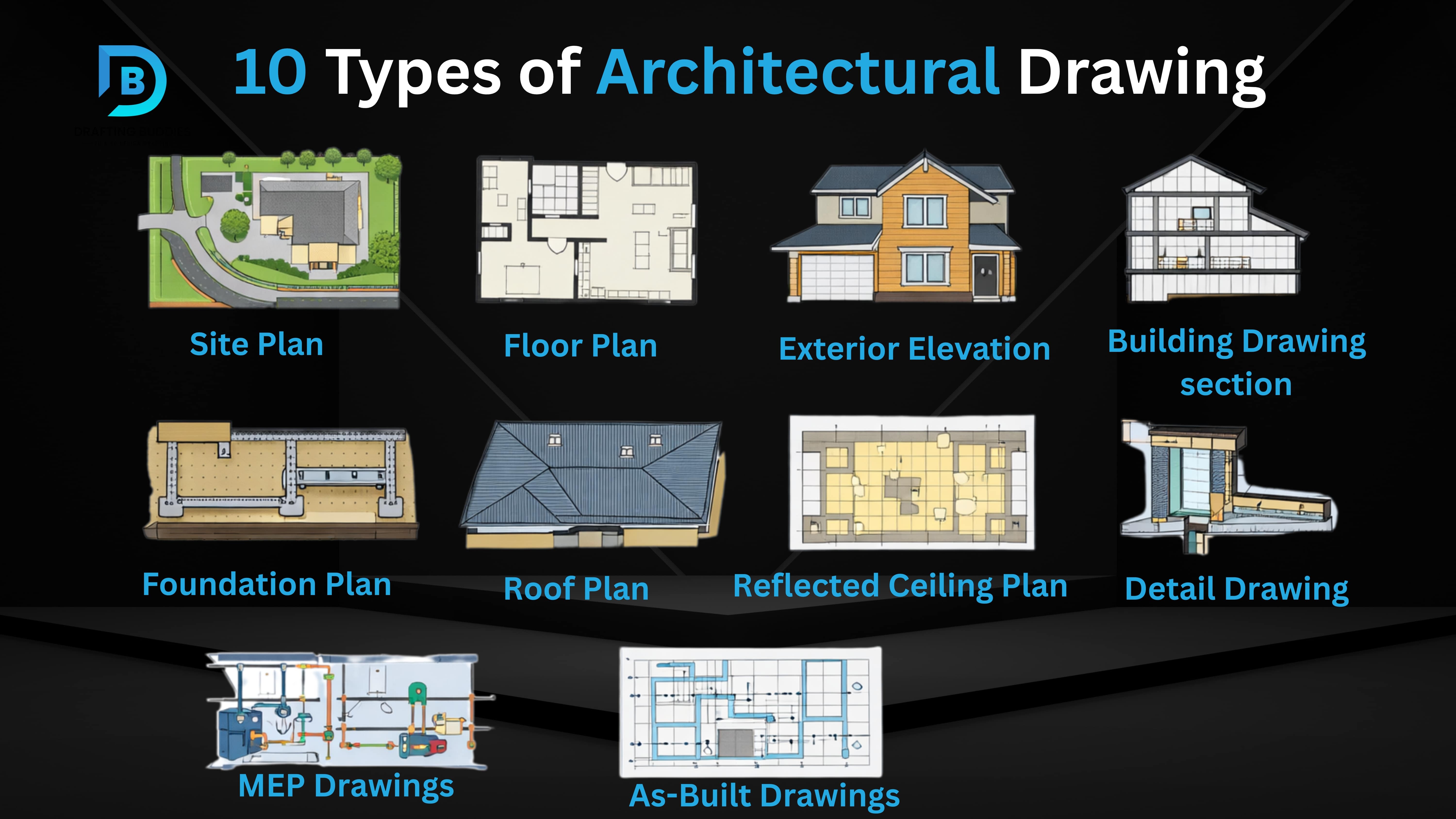
Every building that rises from the ground, whether a modest family home or a 40-story commercial tower, begins not with concrete or steel but with drawings. Architectural drawings are the universal language of construction: precise, standardized documents that communicate design intent, structural requirements, and system layouts to every professional on a project.
For architects, contractors, engineers, and property owners alike, understanding these drawing types is fundamental. Each type serves a distinct purpose, adheres to established conventions, and plays a critical role in ensuring that a project is built correctly, safely, and in compliance with local codes.
This guide covers all 10 essential types of architectural drawings used in modern construction, what each one shows, who uses it, and why it matters.
1. Site Plan
A site plan is the starting point of any construction project. It provides a scaled, top-down view of the entire property, showing how the proposed building relates to its surroundings, boundaries, and infrastructure.
What It Includes
- Property boundaries and legal setbacks.
- Building footprint and orientation.
- Driveways, walkways, and parking areas.
- Utility connections: water, sewer, and electrical.
- Landscaping, grading, and drainage patterns.
Why It Matters
The site plan is typically the first document reviewed during the permit application process. It establishes that the proposed development complies with zoning regulations, setback requirements, and environmental restrictions. Without an accurate site plan, no building permit will be issued.
2. Floor Plan
The floor plan is one of the most widely recognized architectural drawings. It represents a horizontal cross-section of the building cut approximately four feet above floor level, revealing the internal arrangement of every level.
What It Shows
- The arrangement of rooms, their dimensions, and how they connect.
- Wall thicknesses and partition types.
- Door and window positions and swing directions.
- Stairways, corridors, and circulation paths.
- Fixed elements such as kitchen islands, bathroom fixtures, and built-in furniture.
Why It Matters
Floor plans are the primary reference document for contractors during framing, drywall, and finish work. They are also essential for interior designers, furniture planning, and real estate listings. A clear, dimensionally accurate floor plan reduces costly mistakes during construction.
3. Exterior Elevation Drawings
Where floor plans show the horizontal layout, elevation drawings show the building's vertical face. An exterior elevation is a flat, orthographic projection of each facade, typically North, South, East, and West, drawn as if viewed from directly in front.
What It Shows
- Exterior materials, cladding, and finishes.
- Roof pitches, eaves, and parapets.
- Window and door heights, sill levels, and header heights.
- Overall building height and floor-to-floor dimensions.
- Architectural features such as columns, awnings, or decorative elements.
Why It Matters
Elevation drawings define the visual character of a building and are critical for client approvals, planning board submissions, and material procurement. They communicate design intent to subcontractors responsible for facade installation.
4. Building Section Drawings
A section drawing slices vertically through the building along a designated cut line, exposing internal relationships that neither the floor plan nor elevation can fully communicate.
What It Shows
- Floor-to-floor and floor-to-ceiling heights.
- Structural framing members: beams, joists, and columns.
- Insulation layers, wall assemblies, and material stacking.
- Mezzanines, double-height spaces, and atrium volumes.
- Staircase geometry and vertical circulation.
Why It Matters
Sections are indispensable for structural engineers and contractors to understand how the building is assembled from the ground up. They are particularly important for multi-story buildings, complex roof structures, and any project involving below-grade construction.
5. Foundation Plan
The foundation plan is a structural document that defines how the building connects to the earth. It is prepared in close coordination with geotechnical reports and structural engineering calculations.
What It Shows
- Footing sizes, depths, and locations.
- Grade beams, pile caps, and slab thicknesses.
- Basement walls and waterproofing specifications.
- Reinforcement bar (rebar) placement and spacing.
- Load transfer paths from superstructure to soil.
Why It Matters
Errors in the foundation plan are among the most expensive to correct once construction has begun. A thorough foundation plan reviewed by a licensed structural engineer ensures the building can safely bear all imposed loads over its entire lifespan.
6. Roof Plan
The roof plan presents the building from directly overhead, focused entirely on the geometry and drainage of the roof system. It is distinct from the site plan, which shows the full property context.
What It Shows
- Roof slopes, pitches, ridges, hips, and valleys.
- Gutters, scuppers, downspouts, and primary drainage.
- Skylights, roof hatches, and mechanical penetrations.
- Rooftop HVAC units, solar panels, and equipment pads.
- Parapet heights and coping details.
Why It Matters
Poor roof design leads to water infiltration, one of the leading causes of long-term building damage. The roof plan is essential for roofing contractors, waterproofing consultants, and MEP engineers who need to coordinate penetrations and drainage.
7. Reflected Ceiling Plan (RCP)
A reflected ceiling plan is drawn as if a mirror were placed on the floor and the ceiling reflected down into it. This convention allows the drawing to maintain the same orientation as the floor plan below, making coordination intuitive.
What It Shows
- Lighting fixture types, locations, and switching zones.
- HVAC supply and return diffusers.
- Sprinkler head positions and fire alarm devices.
- Soffits, coffers, tray ceilings, and height changes.
- Ceiling material transitions and grid layouts.
Why It Matters
The RCP is the primary coordination document for mechanical, electrical, and plumbing contractors working above the ceiling plane. Without it, trades work independently, and conflicts are only discovered after installation, leading to expensive rework.
8. Detail Drawings
While floor plans and elevations communicate the big picture, detail drawings zoom in on specific assemblies at a much larger scale, typically 1:10 or 1:1, to eliminate any ambiguity about how a component is constructed.
Common Detail Types
- Window and door jamb, head, and sill conditions.
- Staircase construction: stringers, treads, and handrails.
- Waterproofing and flashing at roof edges and transitions.
- Structural steel connections and bolted assemblies.
- Interior millwork: cabinetry, shelving, and trim profiles.
Why It Matters
Contractors rely on detailed drawings to execute work correctly without guessing. In fabrication and prefabrication workflows, these drawings are often converted into shop drawings for manufacturing. The level of detail in these drawings directly correlates with construction quality.
9. MEP Drawings (Mechanical, Electrical & Plumbing)
MEP drawings document the three essential building systems that make a structure functional and habitable. These are produced by specialist engineers and must be carefully coordinated with each other and with the architectural drawings.
Mechanical (HVAC)
- Ductwork routing and sizing.
- Air-handling units, fan coil units, and exhaust fans.
- Thermostat zones and control sequences.
Electrical
- Panel schedules and circuit routing.
- Outlet, switch, and fixture locations.
- Data, communications, and low-voltage systems.
Plumbing
- Cold and hot water supply lines.
- Drain, waste, and vent (DWV) systems.
- Gas lines and appliance connections.
Why It Matters
MEP systems represent 30 to 50 % of the total construction cost of most commercial buildings. Clash detection, identifying where ducts, pipes, and conduits conflict, is performed using 3D coordination models built from MEP drawings. Poorly coordinated MEP drawings are one of the most common causes of construction delays.
10. As-Built Drawings
As-built drawings, sometimes called record drawings, are created at the conclusion of a project. They document the building exactly as it was constructed, capturing every deviation, substitution, and field adjustment made during the construction process.
What They Record
- Final wall, column, and partition locations.
- Actual pipe, conduit, and duct routes as installed.
- Equipment locations and model numbers.
- Structural changes approved during construction.
- All field modifications and approved submittals.
Why It Matters
As-built drawings are the owner's permanent record of their building. They are essential for future renovations, building maintenance, emergency response planning, and regulatory inspections. Many building contracts and public projects legally require their delivery as a condition of final payment.
Quick Reference: All 10 Drawing Types
| Drawing Type | Primary Purpose | Typical Scale |
|---|---|---|
| Site Plan | Property layout & zoning compliance | 1:200 – 1:500 |
| Floor Plan | Internal room layout & dimensions | 1:50 – 1:100 |
| Exterior Elevation | Facade appearance & materials | 1:50 – 1:200 |
| Building Section | Vertical relationships & structure | 1:20 – 1:50 |
| Foundation Plan | Structural base & footings | 1:50 – 1:100 |
| Roof Plan | Roof geometry & drainage | 1:100 – 1:200 |
| Reflected Ceiling Plan | Ceiling systems & MEP coordination | 1:50 – 1:100 |
| Detail Drawing | Precise assembly instructions | 1:1 – 1:10 |
| MEP Drawings | Mechanical, electrical & plumbing systems | 1:50 – 1:100 |
| As-Built Drawings | Final record of construction | 1:50 – 1:100 |
Conclusion
Architectural drawings are not simply paperwork; they are the foundation upon which every successful construction project is built. Each of the ten types covered in this guide serves a distinct and irreplaceable role, from establishing legal compliance with the site plan to providing a permanent ownership record with the As-built drawings.
Understanding these drawing types helps property owners ask the right questions, helps contractors execute work with confidence, and helps architects communicate their vision with clarity. When each drawing is produced to a professional standard and kept current throughout the project lifecycle, the result is fewer conflicts, lower costs, and a better-built structure.
Whether you are embarking on a residential renovation or a large commercial development, investing in quality architectural documentation from the outset is one of the highest-return decisions you can make.
Recent Blogs
FAQs:
You Ask, We Draft