HVAC Drafting Services USA: How AI and Automation are
Transforming MEP Design in 2026
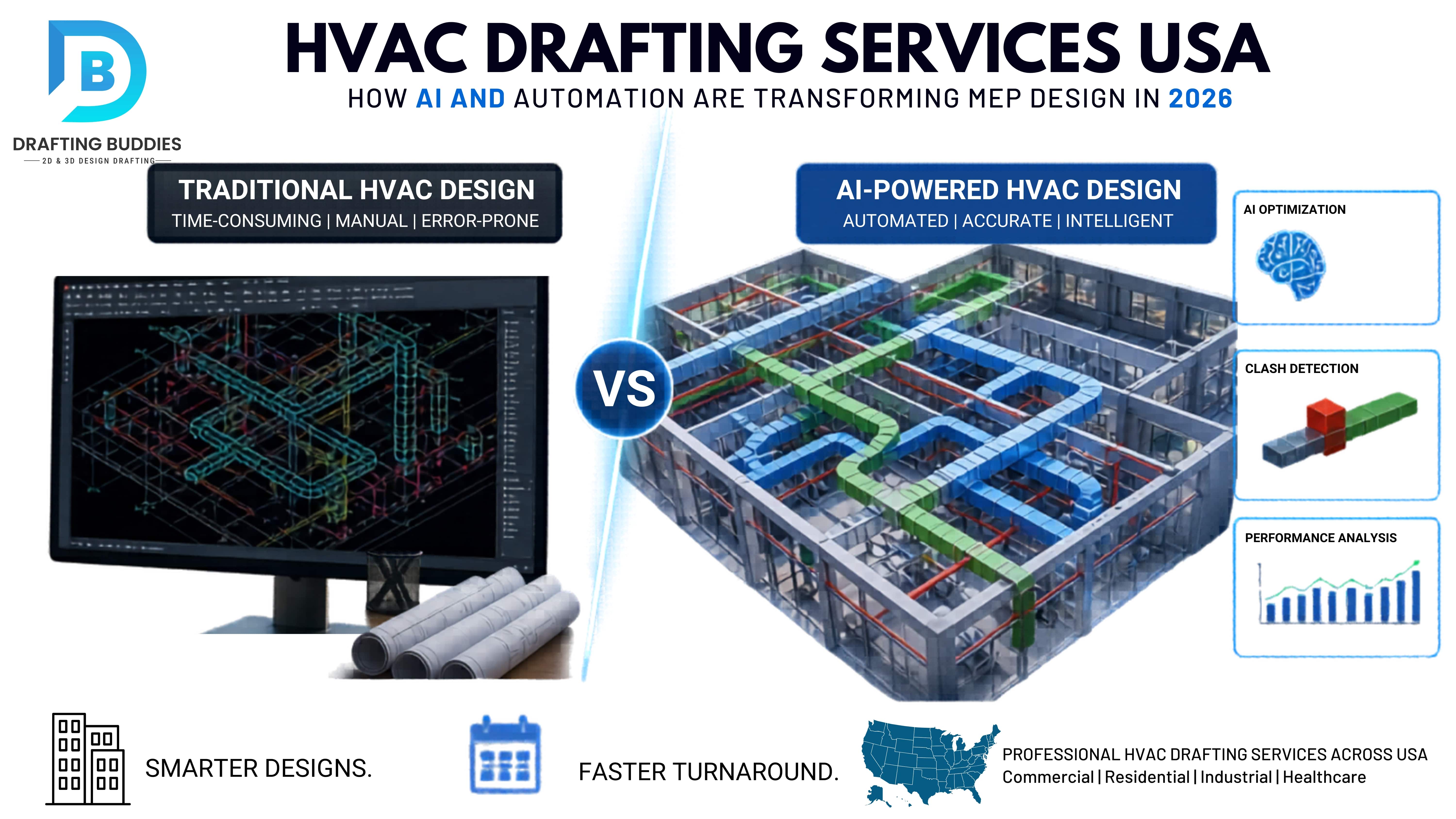
This blog explains how HVAC drafting services in the USA have evolved with AI, BIM, and automation, making HVAC CAD drawings, duct design, and shop drawings faster, more accurate, and better coordinated than traditional methods. It highlights real construction failures caused by poor coordination and outdated load calculations, showing how small drafting errors can lead to major project delays and cost overruns.
It also explains the modern workflow of HVAC drafting, including BIM integration, load calculations, 3D duct routing, clash detection, and automated shop drawing production. The role of AI is shown as a support tool that improves speed and accuracy but cannot replace human engineering judgment.
Overall, the blog emphasizes that professional HVAC drafting services are essential for accurate design, smooth installation, and efficient building performance across commercial, residential, and industrial projects.
Why HVAC Drafting Is No Longer Just About Drawing Lines
If you work in construction, engineering, or facilities management in the United States, you already know that HVAC systems are the backbone of any building, commercial, industrial, or residential. What you may not fully realize is how dramatically HVAC drafting services have evolved over the past few years.
Gone are the days when a drafter would sit at a workstation, manually sizing ducts on a floor plan and hoping the measurements held up during installation. Today, HVAC drafting services in the USA combine AI-assisted software, BIM coordination, and cloud-based collaboration to produce shop drawings, duct layouts, and system designs that are more accurate, faster to deliver, and significantly less likely to cause costly field rework.
This blog breaks down exactly what modern HVAC drafting services involve, why accuracy in HVAC CAD drawings matters more than most project managers think, and what contractors, engineers, and architects should look for when they outsource HVAC drafting services in the USA.
What Are HVAC Drafting Services, and What Do They Actually Produce?
HVAC drafting services refer to the professional preparation of technical drawings, layouts, and schematics that guide the installation of heating, ventilation, and air conditioning systems in a building. These services are typically delivered by MEP (mechanical, electrical, and plumbing) engineering firms, specialized drafting companies, or offshore teams working under the direction of a licensed engineer or contractor.
The deliverables produced under HVAC drafting services include:
- HVAC CAD drawings: Precise 2D layouts of equipment, ductwork, pipe runs, and system components created in AutoCAD MEP or similar platforms
- HVAC shop drawings: Fabrication-ready drawings used by sheet metal fabricators and field installers, showing exact dimensions, material specs, and connection details
- HVAC duct design drawings, Airflow diagrams showing supply, return, and exhaust routes, duct sizes, and pressure loss calculations
- HVAC system design packages, full design documentation including equipment schedules, load calculations, control diagrams, and riser drawings
- HVAC coordination drawings: Combined MEP drawings that overlay mechanical systems with structural, electrical, and plumbing elements to identify spatial conflicts
- HVAC as-built drawings, post-construction documentation reflecting actual installed conditions
Each of these outputs requires a different level of technical expertise. HVAC CAD drawings for commercial buildings, for example, must comply with ASHRAE standards, local codes, and the architect's space planning while simultaneously accommodating ceiling height restrictions, beam penetrations, and fire-rated assemblies. Producing accurate drawings is not a clerical task. It is a technical one.
The Real Cost of Inaccurate HVAC CAD Drawings: Two Real-World Scenarios
Most project delays related to mechanical systems do not happen because the HVAC equipment was wrong. They happen because the HVAC CAD drawings were incomplete, outdated, or never properly coordinated with other trades. Here are two realistic scenarios that illustrate this problem clearly.
Scenario 1: The Clash That Delayed a 12-Story Office Tower
A general contractor in Chicago was overseeing the MEP rough-in on a 12-story commercial office building. The HVAC system had been designed and drawn independently by a mechanical engineer, while the structural engineer worked on a separate BIM model. When field crews reached the 7th floor, they discovered that a major supply air trunk duct approximately 24 inches by 36 inches ran directly through a steel transfer beam that was not reflected in the mechanical drawings.
The result: three weeks of field delay, $47,000 in unplanned labor costs to reroute the duct around the beam, and a change order dispute between the GC and the mechanical subcontractor. The root cause was simple: the HVAC duct design drawings had never been clash-detected against the structural model.
Had the project used proper HVAC coordination drawings with MEP and structural overlays, a standard output of modern HVAC drafting services, this conflict would have been caught during design review, not during installation.
Scenario 2: Undersized Ductwork in a Hospital Renovation
A mechanical contractor in Texas was brought in to replace the air handling system in a 60-bed hospital wing. The original HVAC drawings were from 1994 and had been partially updated in 2008, but the load calculations had never been formally revised after a 2015 renovation that added an imaging suite and a procedure room to the same air handler zone.
When the new AHU was installed and commissioned, supply airflow to the imaging suite was 30% below design, a critical issue in a healthcare environment where pressurization relationships and air changes per hour are regulated. The ductwork serving that zone had to be partially torn out and upsized. Total cost: $63,000 in materials and labor, plus a 5-week commissioning delay.
The problem was not the equipment. It was that the HVAC system design had relied on outdated load calculations that no one had revisited. Proper HVAC engineering services, including a full load recalculation before drafting began, would have prevented this entirely.
These are not edge cases. They are representative of the kind of issues that occur on construction projects across the United States every week. And they are almost entirely preventable with accurate, well-coordinated HVAC drafting services.
How Modern HVAC Drafting Software Has Changed the Workflow
Ten years ago, most HVAC drafting was done in AutoCAD using 2D linework. A drafter would receive an architectural floor plan, import it as a reference underlay, and manually draw the duct layout on top of it. Duct sizing was done using manual calculations or a separate program, and the results were typed into the drawing. Coordination with structural and electrical happened in physical drawing review meetings.
Today, the workflow has fundamentally changed. Here is what a modern HVAC drafting services workflow looks like for a mid-size commercial project:
Step 1 : BIM Model Import: The architect and structural engineer share their Revit models. The HVAC design team imports these into Revit MEP or AutoCAD MEP as linked files, ensuring the mechanical model is always working against the most current architectural geometry.
Step 2 Load Calculations: Using tools like Trane TRACE 700, HAP (Hourly Analysis Program), or Revit's built-in energy tools, the team runs heating and cooling load calculations based on building orientation, envelope performance, occupancy schedules, and equipment heat gain. These calculations directly determine equipment sizing and airflow requirements for the HVAC system design.
Step 3 Duct Layout Generation: Ductwork is routed in 3D within the BIM model, respecting ceiling height clearances, structural penetration limitations, and coordination corridors established for other trades. Modern HVAC drafting software can automatically flag routing paths that violate code-required clearances.
Step 4: Clash Detection: The HVAC model is run through Autodesk Navisworks or similar clash detection software against structural, electrical, and plumbing models. Hard clashes (physical intersections) and soft clashes (clearance violations) are identified, logged, and resolved before any fabrication begins.
Step 5 Shop Drawing Production: Once the coordination model is clean, shop drawings are extracted from the BIM model. These HVAC spool drawings include spooling sheets for prefabrication, hanger point locations, connection details, and equipment installation clearances. They are the documents that actually go to the field.
Step 6 Documentation Package: The final HVAC drawings package includes duct layout plans, sections, equipment schedules, control diagrams, and sequence of operations, everything an installing contractor, AHJ inspector, and commissioning agent needs.
The key difference between this workflow and the older approach is coordination. Modern HVAC drafting services are not done in isolation. They are part of an integrated BIM process where every trade is working in the same shared model, and conflicts are resolved digitally before they become physical problems in the field.
AI in HVAC Drafting: What It Actually Does (and What It Cannot Do)
The term AI-assisted HVAC drafting workflows has been used loosely in recent years. It is worth being specific about what artificial intelligence actually contributes to HVAC drafting services today and where human expertise remains essential.
What AI Genuinely Automates
AI tools in HVAC drafting software are primarily useful for pattern recognition and rules-based automation. In practical terms, this means:
- Automated duct routing suggestions based on airflow requirements, room geometry, and pre-defined routing preferences
- Real-time clash detection that flags conflicts as the designer works rather than waiting for a formal Navisworks review
- Load calculation assistance that pulls building geometry directly from the BIM model, reducing manual data entry and transcription errors
- Equipment selection support that cross-references calculated loads against manufacturer catalogs to suggest appropriately sized units
- Automated dimensioning and annotation of HVAC CAD drawings, reducing drafting time significantly
What AI Cannot Replace
AI cannot replace engineering judgment, the ability to look at a set of project conditions, understand the constraints that are not written in any specification, and make a decision that balances performance, constructability, budget, and long-term maintainability.
Consider the hospital renovation scenario described earlier. An AI tool could correctly calculate that the imaging suite requires 1,200 CFM of supply air. But it takes an experienced mechanical engineer to recognize that the pressurization relationship between that suite and the adjacent corridor is critical for infection control and that the control sequence needs to maintain positive pressure even during a fire alarm override. That is a judgment call built on years of healthcare HVAC experience, and no software makes it automatically.
Similarly, HVAC duct design for residential projects requires understanding how homeowners actually use their spaces. A technically correct duct layout may still produce comfort complaints if it fails to account for a south-facing great room that gets 40% more solar gain than the load calculation assumed, or a kitchen range hood that is exhausting more air than the system is bringing in.
The professionals who thrive in this environment are not the ones who resist AI tools, nor the ones who trust them blindly. They are the ones who understand what these tools are doing, verify their outputs, and apply the engineering judgment that software cannot replicate.
HVAC Duct Design: The Technical Foundation of Every System
Of all the outputs produced by HVAC drafting services, the duct design drawings are the ones most directly tied to whether a system will actually perform as intended. Getting the ductwork right is not just about fitting pipes through a ceiling. It is about ensuring that every room in a building receives the right quantity of air at the right velocity consistently, efficiently, and quietly.
There are three primary methods used for HVAC duct sizing in the USA:
Equal Friction Method: The most common method for commercial projects. Duct sizes are selected so that the pressure drop per unit length is constant throughout the system. This makes it relatively straightforward to balance airflow across multiple branches.
Velocity Reduction Method: Used primarily in low-velocity residential and light commercial systems. Duct velocity is progressively reduced as branches split off the main trunk. Simpler to design but less precise in larger systems.
Static Regain Method: Used in large commercial and industrial applications where duct runs are long, and airflow quantities vary significantly between branches. The static pressure regained as air slows at each branch transition is used to maintain balance throughout the system. More complex to design but produces better performance in large systems.
The choice of sizing method matters because it affects not just the duct dimensions but also the equipment selection, the control strategy, and the long-term energy efficiency of the building. An HVAC system design that uses an inappropriate sizing method for its application will underperform, and in many cases, the building owner will never understand why their energy bills are higher than expected or why certain zones are always uncomfortable.
This is why HVAC engineering services from an experienced firm are worth the investment, not just for the drawings, but for the engineering thinking behind them.
Outsourcing HVAC Drafting Services in the USA: What to Know Before You Do
For many contractors and engineering firms, outsourcing HVAC drafting services is a strategic decision that reduces overhead, improves turnaround times, and allows in-house staff to focus on higher-value work. But outsourcing HVAC drafting to the wrong partner can create more problems than it solves.
Here is what to evaluate when considering whether to outsource HVAC drafting services in the USA:
1. Software Compatibility
Confirm that the outsourcing partner works on the same platforms you use, Revit MEP, AutoCAD MEP, or CADmep. File format mismatches cause delays and can introduce errors when drawings are translated between systems. If a partner delivers DWG files when you need RVT, the coordination value of their work is significantly reduced.
2. Code Knowledge and Standards Compliance
HVAC CAD drawings for commercial buildings in the United States must comply with ASHRAE 90.1 (energy efficiency), ASHRAE 62.1 (ventilation), NFPA 90A (ductwork installation), and applicable local amendments to the International Mechanical Code. An outsourcing partner unfamiliar with US codes may produce drawings that look complete but fail inspection or require significant revision.
3. MEP Coordination Capability
HVAC coordination drawings with MEP require the drafting team to work within a shared BIM environment, understand the coordination workflow, and communicate clearly with structural and electrical drafters. Verify that your outsourcing partner has genuine experience with multi-trade coordination, not just standalone duct layout drafting.
4. Shop Drawing Experience
HVAC shop drawings for fabrication are different from design intent drawings. They must include specific information that fabricators need: sheet metal gauge thickness, joint type, seam specifications, hanger locations, and access door placements. A drafting partner that produces clean design drawings but never produces shop drawings for a sheet metal fabricator will create problems at the fabrication stage.
5. Communication and Review Process
The best outsourcing relationships are collaborative, not transactional. Look for a partner that provides a clear review cycle, responds to RFIs (Requests for Information) promptly, and tracks revision history carefully. HVAC drafting services for engineers and architects require a partner who understands the professional workflow, not just the technical drawing requirements.
HVAC Drafting for Different Project Types
HVAC Drafting Services for Commercial Buildings
Commercial HVAC projects in office buildings, retail centers, hotels, and healthcare facilities are the most demanding in terms of coordination complexity, code compliance, and documentation requirements. HVAC CAD drawings for commercial buildings typically include multiple system types (VAV, FCU, chilled water, and DX), complex zoning strategies, and extensive controls integration. The coordination drawings required for a commercial building often involve dozens of trades and hundreds of potential clash points.
HVAC Drafting Services for Residential Projects
Residential HVAC drafting is less complex in terms of system scale, but precision still matters enormously. A poorly designed duct layout in a residential system will result in comfort complaints, uneven temperature distribution, and excessive energy use. HVAC drafting services for residential projects should include accurate Manual J load calculations (the ACCA standard for residential load calculations in the USA), Manual D duct design, and equipment selection that matches the actual loads, not based on rules of thumb.
HVAC Drafting Services for Industrial and Mission-Critical Facilities
Data centers, pharmaceutical manufacturing facilities, cleanrooms, and food processing plants have HVAC requirements that go well beyond comfort. These projects require specialized HVAC system design expertise, understanding of pressurization relationships, redundancy requirements, filtration standards, and process-specific environmental conditions. HVAC modeling services using dynamic simulation tools are often required to validate system performance before construction.
HVAC Controls and Their Integration with Drafting Documentation
One area that is frequently underrepresented in HVAC drafting service packages is the controls documentation. HVAC controls systems include thermostats, sensor, actuators, variable frequency drives, and building automation system programming that determine how a system operates are often treated as a separate scope from the mechanical drawings. This is a mistake.
A well-coordinated HVAC drafting package includes control diagrams that show the relationship between each piece of equipment and its control devices, sequences of operation that describe exactly how the system responds to changing conditions, and point lists that the BAS (Building Automation System) programmer uses to configure the system.
Without this documentation, even a perfectly designed and installed mechanical system will underperform because the controls will not be configured to operate it correctly.
Modern HVAC CAD services increasingly include controls schematic drafting as part of the standard deliverable, not as an afterthought. This integration between mechanical design and controls documentation is one of the clearest indicators of a sophisticated HVAC drafting services provider.
HVAC Maintenance Services and the Role of As-Built Documentation
The drawings produced during design and construction do not stop being useful after the building opens. HVAC maintenance services depend on accurate as-built documentation to diagnose problems, plan preventive maintenance, and manage equipment replacements over the life of the building.
Unfortunately, as-built HVAC drawings are one of the most commonly neglected deliverables in construction. Field changes are made during installation, but the drawings are never updated. Years later, a building engineer trying to diagnose an airflow problem is working from drawings that reflect the design intent, not the actual installed conditions and the discrepancies are invisible until something goes wrong.
Progressive owners and facility managers are increasingly requiring that HVAC drafting services include a formal as-built drawing process, where field markup sheets are submitted throughout construction and incorporated into the final drawing package before substantial completion. This practice extends the useful life of the building's documentation and reduces the long-term cost of HVAC maintenance services.
Conclusion: Accurate HVAC Drafting Is a Strategic Investment, Not an Administrative Cost
The construction industry in the United States loses billions of dollars annually to rework unplanned labor and material costs that result from errors and conflicts that should have been caught during design. A significant portion of that rework originates in mechanical systems, and a significant portion of that traces back to HVAC drawings that were incomplete, uncoordinated, or based on outdated information.
Investing in professional HVAC drafting services is not just about producing drawings. It is about producing the right drawings, accurate, coordinated, code-compliant, and fabrication-ready, so that the workflows can proceed without interruption.
Whether you are an HVAC contractor looking to outsource your drafting workflow, an MEP engineering firm seeking to expand your BIM capabilities, or an architect trying to understand what your mechanical engineer should actually be delivering, the quality of HVAC drafting services on your project will directly affect the quality of the building that gets built.
Choose your HVAC drafting partners carefully. Verify their software, their code knowledge, their coordination experience, and their shop drawing capability. And recognize that the firms delivering the best HVAC drafting services in the USA are not cutting corners; they are building systems that work, on paper first, so they work in the field.
Recent Blogs
FAQs:
You Ask, We Draft