10 HVAC Duct Layout Mistakes That Cost Projects | How to Avoid Them
Poor HVAC duct layout decisions made at the drafting table are the root cause of most costly on-site rework, system underperformance, and long-term maintenance headaches. The blog outlines 10 critical mistake from ignoring spatial clashes with other trades and getting airflow calculations wrong, to overlooking noise control, skipping maintenance access planning, and sticking to 2D drawings on complex builds. Each mistake carries a real financial consequence, with rework costs ranging from thousands to tens of thousands of dollars. The core message is straightforward: accurate, well-coordinated HVAC drafting using the right tools whether Manual D calculations, BIM clash detection, or 3D modelling is far cheaper than fixing problems after installation begins. Good drafting isn't just a technical exercise; it's project risk management.
Walk onto most construction sites where HVAC rework is happening, and you'll find the problem started long before a single piece of ductwork was installed. It started at the drafting table.
In 2023, the Air Conditioning Contractors of America (ACCA) reported that improper duct design is a leading cause of HVAC callback issues, contributing to uneven temperatures, excessive energy use, and premature equipment wear. Yet many of these failures trace back to a handful of preventable mistakes made during the layout and drafting phase.
This article breaks down the 10 most critical HVAC duct layout errors, what causes them, what they actually cost, and how modern drafting practices prevent them before installation begins.
Quick note: Whether you're using AutoCAD MEP, Revit, or a specialist HVAC CAD platform, these principles apply across every tool and project type.
1. Ignoring Spatial Constraints The Clash Nobody Caught
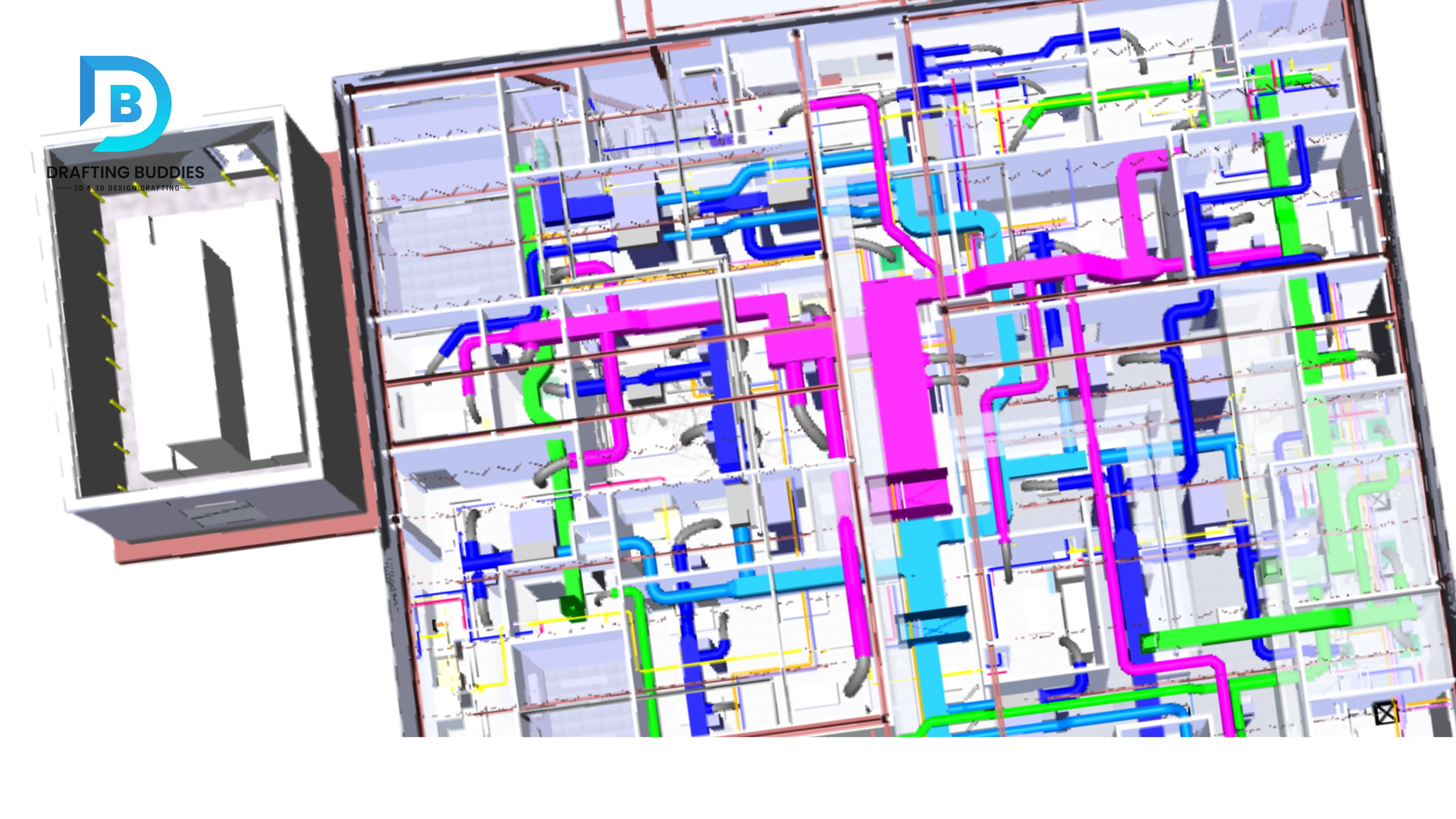
Ductwork doesn't exist in a vacuum. It shares ceiling space with electrical conduits, fire suppression pipes, structural beams, and plumbing lines. Drafters who design HVAC duct layouts without 3D coordination with other trades are essentially designing with their eyes closed.
The consequence: On-site clashes that force expensive rerouting, project delays, and budget overruns. A single undetected duct clash can cost $2,000-$15,000 in rework, depending on the stage of the build when it's discovered.
The fix:
- Use BIM-integrated HVAC drafting (Revit MEP, AutoCAD MEP) with active clash detection enabled
- Run clash detection reports before issuing for construction, not after
- Coordinate with structural, electrical, and plumbing models in a federated model review
2. Getting Airflow Calculations Wrong
Duct layout is not just a routing exercise; it is fundamentally an airflow engineering problem. Every branch, every bend, every transition affects the system's ability to deliver the right volume of air to the right zone at the right pressure.
The fix:
Common calculation errors include:
- Undersizing main supply trunks, creating high-velocity noise and pressure drop
- Ignoring the equivalent length of fittings when calculating total pressure loss
- Failing to account for duct leakage in pressurized systems (ASHRAE 90.1 requires leakage testing for commercial projects)
Industry benchmark: Per ASHRAE Handbook HVAC Systems and Equipment, duct velocity in main supply trunks should generally remain between 1,000-1,600 FPM for low-noise commercial applications. Exceeding this without acoustic treatment is a design defect.
Perform Manual D calculations (residential) or ASHRAE duct design methods (commercial) before finalizing duct sizes. Use software like Wrightsoft, Elite RHVAC, or the ASHRAE Duct Design module to verify sizing rather than relying on rules of thumb.
3. Inconsistent Duct Sizing Across the Drawing Set
This is one of the most common and most overlooked HVAC drawing errors. A drafter sizes ducts correctly for one zone but uses a different methodology or load assumption for another, producing inconsistent cross-sections across the same system.
The fix:
Signs this has happened:
- Velocity spikes in one branch while others underperform
- Balancing contractors are unable to hit design flow rates without excessive damper restriction
- The system requires re-commissioning after installation
Establish a duct sizing schedule at the project outset and link it to the load calculation output. Every duct segment from the AHU main to the last flex drop should be sized from the same data source, with changes documented and version-controlled.
4. Designing for Installation, Not for Maintenance
A duct layout that can be installed in two weeks but requires three tradespeople and a scissor lift for every filter change is a bad design. Yet maintenance access is routinely treated as an afterthought in HVAC drafting, squeezed out by ceiling height constraints and coordination battles with other trades.
The fix:
What gets forgotten:
- Access panels sized for the equipment they serve (a 450mm panel won't allow a belt change on a large AHU)
- Clear minimum working clearances around coils, fans, and heat exchangers per manufacturer specs
- Valve and damper actuator positions that are accessible without removing adjacent ductwork
Real-world example: A commercial project in the UK retrofitted 23 additional access panels post-completion because the original design had none between the AHU and the final diffusers, adding over GBP 18,000 to the project cost.
During the design review stage, walk the maintenance route mentally, where does a technician stand to service each component? Mark access requirements on the HVAC drawings and coordinate their positions with ceiling tile grids and other finishes.
5. Overlooking Noise: The Invisible Complaint
Duct noise is the HVAC complaint that tenants notice every day but rarely appears on a snag list until a building is occupied. It is also almost entirely preventable at the design stage.
The fix:
The most common noise sources in poorly designed duct layouts:
- High-velocity air at supply grilles due to undersized terminal connections
- Turbulence from abrupt direction changes, an unlined square elbow, is particularly bad
- Cross-talk between adjacent rooms through shared ductwork (a critical issue in healthcare and education projects)
Specify duct liner (typically 25 mm acoustic lining) for first-meter runs off AHUs. Use radius elbows or turning vanes rather than square 90-degree bends. Where cross-talk is a risk, design acoustic attenuators and specify the required insertion loss in the specifications.
6. Overcomplicating the Duct Route
There is a tendency in complex buildings to treat the duct route as a puzzle to be solved, weaving around every obstacle regardless of the pressure penalty. The result is a system full of unnecessary bends, offsets, and transitions, each one adding resistance that the fan must overcome permanently.
Every unnecessary 90-degree elbow in a duct system adds resistance equivalent to roughly 0.9-1.2 meters of straight duct (depending on fitting type). A route with 10 avoidable elbows is adding 9-12 meters of phantom duct to your system's resistance calculation.
The fix:
Before finalizing a duct route, challenge every bend. Can a structural coordination request move a beam slightly? Can a slightly lower duct reduce three bends to one? The simplest route that meets all constraints is almost always the best route.
7. Leaving Smart Controls Out of the Drawing
Modern HVAC systems are designed to respond dynamically to occupancy, CO2 levels, outdoor temperature, and time-of-day schedules. But sensors cannot be retrofitted effectively after the ductwork is installed; their positions need to be designed in.
The fix:
What drafters frequently omit:
- Zone temperature sensor locations relative to supply and return air paths
- CO2 sensor positions in VAV systems (should be 900 mm-1800 mm above floor in the occupied zone, not in the return duct)
- Conduit routes and junction boxes for BMS wiring to actuators and dampers
Work from the controls specification (if available at the design stage) or coordinate with the BMS engineer before finalizing the duct layout. Include sensor and actuator locations on HVAC CAD drawings so they are installed the first time.
8. Poor Coordination with Other Trades
HVAC doesn't stand alone. On any multi-trade project, a duct layout produced in isolation is a duct layout headed for clashes. Yet some drafters still produce HVAC drawings without reference to the latest electrical or structural drawings, sometimes because of poor project management, sometimes through habit.
The consequences are predictable: site disputes, costly variations, and the perennial 'who moves first' standoff between HVAC and electrical installers on site.
The fix:
Establish a formal coordination protocol at project start. At a minimum, run a clash detection report against current electrical and structural models before each HVAC drawing issue. On larger projects, BIM coordination meetings with all trades present are standard practice for exactly this reason.
9. Designing Only for Today's Requirements
Buildings are rarely static. Tenants change, occupancy levels fluctuate, and building uses evolve. An HVAC system designed with no spare capacity and no provision for future modifications will become a liability within a decade.
The fix:
Future-proofing considerations are often skipped at the drafting stage:
- No spare capacity on main supply and extract trunks for future branch connections
- No provision for additional AHU connections at the plant room level
- Duct routes that block future structural openings identified on the architect's plans
Review the client's brief for any future expansion provisions and reflect them in the duct layout. A modest increase in main trunk size costs very little at installation and avoids a full system redesign when the client adds a new floor in five years.
10. Sticking to 2D When the Project Demands 3D
2D HVAC drawings still have their place in simple residential projects and small commercial fit-outs but they have significant limitations on complex builds. Coordinating a data centre ceiling plenum or a hospital operating suite with 2D drawings is asking for problems that 3D modelling would have caught in an afternoon.
The fix:
The limitations of 2D-only HVAC drafting:
- No automatic clash detection, clashes must be spotted manually by experienced reviewers
- Difficult to communicate vertical offsets and multi-level routing to installation teams
- Cannot be federated with structural and MEP BIM models for coordination
Match your drafting method to the project's complexity. For any project with significant MEP coordination requirements, typically commercial projects over 1,000 m2, healthcare, education, and data centre work, 3D HVAC modelling in Revit MEP or AutoCAD MEP is not a luxury; it is a risk management tool.
Quick Reference: Mistake, Risk, and Fix
| Mistake | Risk if ignored | Primary fix |
|---|---|---|
| Spatial clashes | Costly site rework, delays | 3D clash detection before issue |
| Airflow errors | System underperformance | Manual D / ASHRAE duct calc |
| Inconsistent sizing | Commissioning failure | Centralised sizing schedule |
| Poor maintenance access | High lifetime service costs | Maintenance route walk-through |
| Noise ignored | Occupant complaints, defects | Lining, attenuators, low velocity |
| Complex routing | High fan energy, pressure loss | Simplify route, audit every bend |
| No smart controls | System cannot be optimised | Coordinate sensors before layout |
| Poor trade coordination | Multi-trade clashes on site | Federated BIM coordination |
| No future capacity | Expensive future upgrades | Reserve trunk capacity upfront |
| 2D on complex builds | Undetected clashes, errors | Use 3D for complex projects |
Final Thought: Good Drafting Is Project Risk Management
The 10 mistakes above are not abstract risks they translate directly into variation orders, commissioning delays, occupant complaints, and maintenance headaches that last the building's lifetime.
The good news is that every single one of them is preventable with the right drafting process, the right tools, and the right coordination habits. An investment in accurate, well-coordinated HVAC drafting is almost always cheaper than the rework it prevents.
FAQs:
You Ask, We Draft